Electric Welding Equipment. Part 2
Description
This section is from the book "Modern Shop Practice", by Howard Monroe Raymond. Also available from Amazon: Modern Shop Practice.
Electric Welding Equipment. Part 2
Westinghouse Arc Welder
The equipment produced by the Westinghouse Electric Company consists of a motor-generator set with switchboards for controlling the machine and the welding circuits. The generator is a 75-volt compound-wound direct-current dynamo and is direct-coupled to a motor of proper capacity and suitable for operation from the power circuit available. Being a constant-potential generator, several operators may work from it at once if proper resistances and switches are provided for each circuit, and work may be done by either the Benardos or Slavianoff processes. An overload circuit breaker is provided for the protection of the generator from the effects of injurious overloads after welding has started.
With this apparatus various classes of welding and cutting may be done and the positive line is connected to the work and the negative to the electrode holder in the usual manner. The amount of current required for the work in hand is regulated by a series of switches which cut in or out sections of an iron grid resistance, and a small portion of the resistance bank is left in circuit continuously to steady the arc. This apparatus has been used almost entirely for graphite cutting and welding until recently when means were provided for using metallic electrodes also. Fig. 62 shows the principal elements properly connected for a single operator, and more circuits would involve the addition of the extra switches, resistances, and electrode holders for each of them. The apparatus for controlling the machine and the welding circuits is mounted on switchboard panels stationed near the motor-generator set.
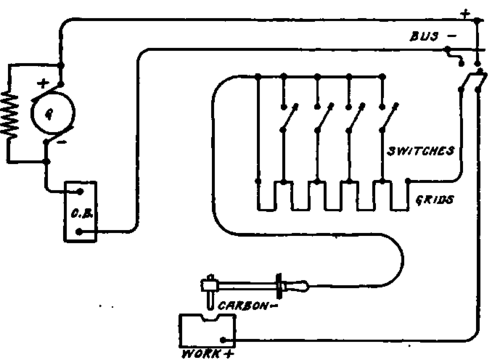
Fig. 62. Wiring Diagram for Weatinghouue Arc Welder.
Lincoln Arc Welder
The Lincoln Electric Company make both motor-generator sets and single-unit machines for welding equipments. both being similar in operation to the Westinghouse outfits just described. The wiring diagram shown in Fig. 63 shows the general connections. The single-unit machines are made as synchronous converters for use on alternating-current circuits or as dynamotors for use on direct-current circuits. The Lincoln dyna-motor differs from others in that there is but one commutator, and the outgoing or generator circuit is taken from two extra brushes located between the motor brushes in the proper position to give current at the proper voltage. The amount of current is varied by varying the strength of the interpoles through switches and by the length of the arc. Resistances are used for varying the current from the alternating-current converters, and also from the motor-generator sets in the usual manner.

Fig. 63. Wiring Diagram for Lincoln Are Welder.
Switchboards are provided containing the apparatus for controlling the welding machine and welding circuits, and an overload circuit breaker is provided to protect the generator from dangerous overloads while working. The overload circuit breaker must be closed by hand if opened. The voltage regulation of the single-unit machines is not quite so good as with their motor-generator sets, of course, but work can be done by either the Benardos or Slavianoff process.
Slemund-Wenzel Welding System
This system is based upon the use of a single shunt-wound direct-current generator for each welding circuit, Fig. 64, and operates on the Slavianoff process.
The principal feature of this system lies in having the generator operating at full load all of the time, and using the current in the arc when welding or dissipating the energy through a resistance in the form of heat when not welding, Fig. 65. The circuit is thrown from the arc to the resistance by means of a solenoid switch, and only one man can work from each machine at one time.
Fig. 64. Single Welder Siamund-WenMl Unit.

Fig. 65. Wiring Diagram for siemund-WaoieI System.
The current is varied to suit different jobs by varying the voltage at the generator, but the current also varies with variations of arc length and tends to vary the amount of metal deposited. This company also uses an electrode holder with a coil embodied in the handle in such a way as to set up a magnetic field around the metallic electrode and arc, on the theory that it helps in depositing the molten metal in the weld, especially or overhead work. This is a doubtful advantage because molten iron and steel are non-magnetic, and in fact are practically so at temperatures as low as 700° centigrade.
Fig. 66. Arc Welding Set with Automatic Overload Relay Courtesy of Genral Electric Company.
General Electric Arc Welder
The welding equipment developed by the General Electric Company, Fig. 66, consists of a compound-wound low-voltage direct-current generator, similar to those previously described, direct-coupled to a motor to suit the power supply, together with a switchboard containing the necessary devices for controlling the machine and the welding circuits. These equipments are made in portable form also. Fig. 67, with the entire outfit mounted on a truck.
Fig. 67. Portable Welding Outfit Courtesy of General Electric Company.

Fig. 68. Wiring Diagram for General Electric Welding Bystom.
By reference to Fig. 68, it will be seen that the current flows from the positive side of the generator to the work through a bank of resistance grids; thence through the arc, electrode, relay, and back to the generator, negative side. The contactor opens and inserts resistance in case the relay is actuated by an overload, and the amount of current required in the arc for welding is varied by a multiple contact switch which cuts in or out sections of the grid resistance. Several men can work at once from machines of this type because of using the constant-voltage system, by adding enough circuit-controlling relays and contactors. The use of the overload relay described prevents injurious overloads on the generator, although the only limitation to current flow in the individual welding circuits of multiple-circuit equipments lies in the resistance in use at the time. In Fig. 69 is shown an operator using the graphite electrode on medium work.
Fig. 69. Operator Using Graphite Electrode on Medium Work Courtesy of General Electiric Company.
Continue to:
My Books

