Details Of Brush Rigging. Plate L. Brush Holder, Stud And Connections
Description
This section is from the book "Modern Shop Practice", by Howard Monroe Raymond. Also available from Amazon: Modern Shop Practice.
Details Of Brush Rigging. Plate L. Brush Holder, Stud And Connections
The previous plates have covered all the principal parts of the machine except the parts for collecting the current from the commutator. Plate L now takes up the details of the brushes and the brush holders. As is usual on such machines the brushes are made of carbon, Fig. 12. The size of the brushes is determined by the designer, as well as the proper number to be used.
Pigtail
The brush must have a "pigtail", Fig. 11, that is, a small cable to connect to the shank of the brush holder in order to get a solid electrical contact between the two. The pigtail is in this case attached to the brush by a copper tube passed through a hole in the brush and through the terminal on the pigtail. Both ends are then spun over, so as to draw the terminal up solidly against the carbon, Fig. 12. In order that the pigtail may clear the spring which holds the brush against the commutator, the slot for it is cut out at an angle. Both sides of the brush are recessed so that the brush can be used until it has gone clear into the holder, due to wear, without interfering with the holding tube or the pigtail.
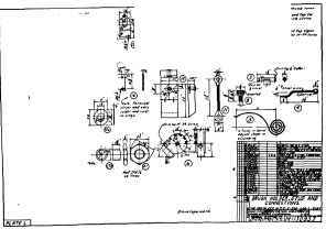
The pigtail itself is called for in the title table only, the dimensions of the terminals and over-all length being given on the drawing.
Brush Holder Shank
The brush holder shank, Fig. 2, is an alloy casting. It must be carefully machined in the brush slot, on the face next the commutator and in the hole for the stud. The other surfaces are simply ground to give a smooth appearance. Note how the shank is split so that it can be clamped to the stud by means of a bolt. Tapped holes are provided for the screws which hold the pigtail and the spring holder. The thumb screw, Fig. 8, for the pigtail, not being a standard machine screw, is detailed.
Spring Holder
The spring holder, Fig. 6, is a rather ingenious punching, only the holes for screws and pin being drilled. Note that this piece is shown in its normal shape, but that development is necessary in order that the dies for the punch press can be made.
The pin, Fig. 5, and lever, Fig. 4, for the spring, Fig. 3, are very simple and do not need explanation.
The above discussion of Plate L has covered the brushes and holder completely. Four of these brushes are needed for each pole of the machine, or twenty-four in all. These must be supported over the commutator so as to make proper contact, and the current must be collected from each set and carried to proper terminal strips. The brush holders and the shifting device are taken up in Plate M. The current-carrying parts - the studs and connecting strips - form the remainder of Plate L.
Continue to:
My Books

