Construction Of Folding Hand Camera
Description
This section is from the book "Cassell's Cyclopaedia Of Mechanics", by Paul N. Hasluck. Also available from Amazon: Cassell's Cyclopaedia Of Mechanics.
Construction Of Folding Hand Camera
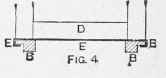
Instructions on making a quarterplate folding hand camera are here given. From 1/4-in. mahogany cut a piece 11 in. by Sin. (A, Fig. 1). The rails BB (Fig. 1), shown in section in Fig. 4, should be fitted as shown 1/2 in. from the front and l 1/2in. from the back. Now cut the two posts CC 1/4in. square and 4in. long, and join with the cross-pieces D and Dl. Cut and bend the plate E (Fig. 4) to tit the rails B; see that it runs smoothly, then screw into D. Now cut the board A (Fig. 1) in two pieces straight across 4in. from the back, and hinge together again underneath. Cut three pieces F, G, and H; F is7 in. by 4 in., G 7 in. by 3in., and H 4in. by 4 1/2 in. In F and G cut the two slots I (the arc being formed with a radius of M) and join all together with A and K, leaving an opening between K and G for the insertion of the dark slide. Next construct a framework L (Fig. 2) (3 in. by 4 in., canting the top and bottom slightly to permit of swing. Fit in this another frame (to which the bellows is fastened) 1/2in. wide at the sides and lin. at the top and bottom. Pivot the sides of the swing frame to F and G at M and N, and fix the thumbscrews I and I1. Having got this to work smoothly, remove the frame and form two tongues Y Y, 5 1/4 in. apart, running from F to G. These form guides or stops for position of dark slide. Now cut two thin brass springs O and screw to the sides of the trame above and below the tongues. Next make the focussing screen 5 1/4n. by 3 7/8in., with iin. rebate for ground glass 4} in. by 3 1/4 in., giving a sight of 4 in. by 3in. At top and bottom of the right-hand end place a screw Z so that it slips under o. Cut four sets of brass joints (as shown in Fig. 3) for attaching the focussing screen to the swing frame. Next fit the door P (Fig. 1) for focussing. Construct two joints Q with springs R, and fit them to the sides of F and G (inside) and to the bottom A. On pulling down the front the spring It forces the side stays up so that the pin s passes into the slot T. The rising front carrying the flange consists of a square of wood, with opening for lens, fitting between the front posts and fastened to a rim of brass at the top through which passes a coarse thread screw worked by a lever J, which, biting against the front post, holds all tightly together in any position. A similar screw fastens the front posts after focussing.
Fig. 3.
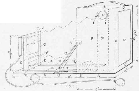
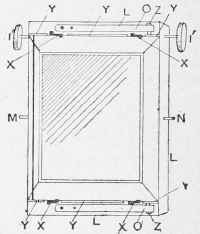
Fig. 2.
Construction of Folding Hand Camera.
Continue to:
My Books

