How To Make A Saw-Sharpening Machine
Description
This section is from the book "Cassell's Cyclopaedia Of Mechanics", by Paul N. Hasluck. Also available from Amazon: Cassell's Cyclopaedia Of Mechanics.
How To Make A Saw-Sharpening Machine
The saw-sharpening machine shown in the accompanying illustrations may be made as follows. Cut from a piece of good hardwood the main standard A (Fig. 1), 12 in. square at the base and 9 in. or 10 in. square at the top. Two pieces i; are fastened to it with bolts, one on each side, being also secured to sleepers fixed in the ground or to the floor-beams, as the case may be. Two pieces C (Fig. 1), 3in. or 4in. by 1 1/2 in., with the grain following the curve as nearly as possible, should be cut .1 piece of oak and similarly fixed with bolts to the main stiudard. At the upper end of each piece there is a bearing D to carry a small shaft which is shown separately at Fig. 2; this shaft has fast and loose pulleys, and a grooved pulley for the band which drives the emery wheel. Cut out a piece of plate-iron to the shape shown at Fig.:;, bore holes in it at EE, and tap them to receive the studs, which are referred to later on. FF indicate the studs that pass through the slots G in Fig. 4. At H (Fig. 3) six holes are bored to receive the stout screws that secure the plate to the oak bearing-pieces (see J, Fig. 1). A narrow ring is riveted on the plate at K (Fig. 3); it should be small enough outside to allow the ring shown at Fig. 4 (see also L, Fig. 1) to pass over it easily, as the latter has to be revolved partially on it. The large centre hole is to allow a gut or rope band to lead to the emery-wheel washers for driving the wheel. After the plate J(Fig. 1) has been shaped, bored, etc., it is heated and bent to a right angle along the dotted line in Fig. 3, as shown in Fig. 1. It is then secured in place. A belt leads from an overhead or intermediate shaft to the pulleys. There are set-offs on the ring at M (Fig. 4), with holes in them to i-eceive the small pins or bolts N (Fig. 1); this ring forms the appliance for canting the swing-carriage X' (Fig. 1) to any desired angle in order to give lead to the saw teeth when they are being gulleted. The swing-carriage is made of iron, and, with the exception of the centres O (Figs. 1 and 5), handles P, and the bolts X (Fig. 1), is in one piece; there are bosses to receive the centres, which are held in place by means of small studs as shown. Between these centres the spindle that carries the emery wheel runs. The handles P P are used for bringing the emery wheel to the saw when it is being gulleted. A wire Q (Fig. 1) passes over the hooked end of the weighted lever R, from which the swing-carriage is suspended. The emery wheel is shown in position in Fig. 5, being held in place by means of nuts screwed tightly against the grooved washers that receive the gut or rope band. The spindle of the wheel, and the centres between which it runs, should be of hardened steel. Fig. 6 is a side view of the iron bar s (Fig. 1) that carries the saw. The slot is to receive a bolt on which washers are placed (see Fig. 1), and between which the saw is secured. The slot allows saws of various diameters to be held. The bar is fixed by means of two studs to a piece T (Fig. 1), shown in plan at Fig. 7. This appliance is hung to the machine by passing the hole D (Fig. 7) over the lower stud E (Fig. 3) and the lower end over the bent piece V (Fig. 1). The saw-plate, whilst being sharpened or gulleted, bears against the straight edge of the piece shown by Fig. 7. Fig. 8 is a front view of the iron bracket W (Fig. 1) that carries the weighted lever R, which is fixed by means of a bolt. This bracket is secured to the plate J by means of two small studs passed through the holes in Fig. 8, and screwed into the top holes E (Fig. 3). A dust-guard may be made from a piece of sheet-iron, and secured hy means of a stud to the front of the swing-carriage X' (Fig. 1). The machine should be given two or three coats of good paint.
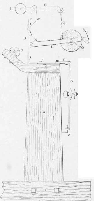
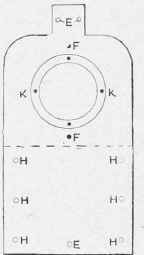
Fig. 3.
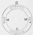
Fig. 4.
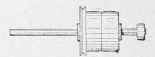
Fig. 2.
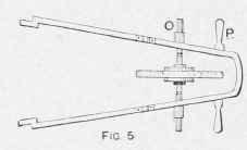
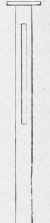
Fig. 6.
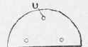
Fig. 7.
Fig. 8. How To Make a Saw-sharpening Machine.
Continue to:
My Books

