Crank
Description
This section is from the book "The Engineer's And Mechanic's Encyclopaedia", by Luke Hebert. Also available from Amazon: Engineer's And Mechanic's Encyclopaedia.
Crank
A short arm or lever fixed to a shaft in any machine, and set in motion by a connecting rod proceeding from some other part of the machine, which has a reciprocating motion to and fro. To obtain a continuous rotatory motion of the crank and shaft it is necessary to fix upon the shaft a fly-wheel of considerably larger radius than the crank, - for when the connecting rod lies in the same direction or right line as the crank, and no longer forms any angle with it, it can have no tendency to move the crank to either side; but the heavy fly-wheel, which, from its greater radius, has travelled much faster than the crank, has acquired a considerable momentum, which urges round the crank when the connecting rod has ceased to impel it, or carries the crank past the dead points, as it is called. Although this means of obtaining a rotatory motion had long been in practice in various machines, as in the turning-lathe, and knife-grinder's wheel, yet it is a singular fact that a considerable time elapsed after the invention of the steam engine ere the same simple and effective method was employed to obtain a rotatory movement from the reciprocating action of the engine beam, whilst several schemes, exhibiting much contrivance and ingenuity, but which were inadequate to the object in view, were from time to time proposed.
By the addition of the crank and fly-wheel to the steam engine, the latter, which before was chiefly used for pumping water, has become generally applicable as a prime mover of machinery, and its utility has, in consequence, been augmented a thousand fold. But the utility of the crank and fly-wheel, as applicable to a steam engine, consists not merely in converting rectilinear into circular motion, but also in gradually destroying the momentum of the piston, and bringing it gently to a state of rest at the end of each stroke. It is a law of nature that all bodies have a natural tendency to preserve their state of motion or of rest, until opposed by some external force. This property of matter occasions a great loss of power in the steam engine, where a massive beam, with all its appendages, have to be reversed at each stroke of the engine; and were it suddenly stopped and reversed when at its greatest velocity, the shock would be so great as speedily to destroy the machinery. The loss of power employed in overcoming the vis inertiae of the beam cannot be avoided, but the shock at the reversal of the motion is prevented by means of the crank, in a manner which will be best explained by the diagram in the margin.
Let a b represent the crank of a steam engine, equal to half the length of the stroke, or half d f, and let d c a c f represent the semicircle through which the crank travels whilst the piston performs a stroke, or moves through the space d f. Now, when the crank is in its present position, the piston is at its greatest speed, and travels with nearly the same velocity as the crank, moving through the space b g whilst the crank passes from a to c. But when the crank moves through the next portion of its revolution c d, equal to the former portion a c, the piston only moves through a space equal to g d in the same time as it before moved through the space b g, which is nearly double g d: hence it is seen that the crank, by diminishing the speed, is admirably adapted for preventing the shock which would be experienced from too sudden a reversal of the motion. A want of a thorough comprehension of the mode in which the fly-wheel and crank operate, has been the origin of many attempts to supersede them. Of these we shall only notice the following, which is the invention of Mr. J.
Apsey.
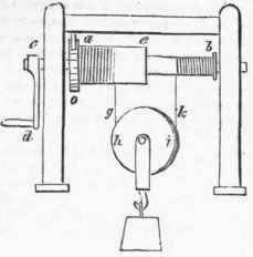

At Fig. 1, page 421, is an elevation of the apparatus; a a is a strong elliptical frame of cast iron, having fixed on each side a toothed rack be. This frame is supposed to be immediately connected to the piston rod of a steam engine or other rectilineal moving force, the motion of which causes the toothed wheels d and e (the wheel c is behind d, as is shown in the edge view of them at Fig. 2,) to revolve on the axis i, which axis communicates its motion and force to whatever machinery may be connected to it. f g are two guide bars, and h j are two guide rings or annular plates, in front of the wheels d and e, which serve to keep their respective parts in their proper places. It will be observed that the frame a a is represented at the lowest point of its descent during such descent it turns round the wheel d by means of the rack g, and at the same time causes a revolution of the axis; by the ascent of the frame the wheel d revolves the contrary way, but it then runs freely upon the axis, so as to have no influence upon it; during the same time the opposite wheel e becomes locked to the axis, and by means of the rack causes the axis to continue revolving in the direction given to it by the previous operation of the wheel d, as; will be best understood by an explanation of Fig. 2, which exhibits the toothed wheels and axis distinct from the frame and side racks.
To each of the wheels d and e are fixed the guide rings h j, and a clutch box k l, which turn with the wheels on a smooth part of the axis, as shown at i in the separate Fig. 3. These wheels are alternately connected to the axis, to give it motion, by means of the clutches o p, which have merely a sliding motion along the axis, and are constantly pressed against the boxes i 4 by means of helical springs q r wound upon the axis, and confined in a case, as represented in the figure. The clutches op have grooves made in them, as shown by the end views of them given in the separate figure o p, through which the stuts s t, Fig. 3, slide, and secure them to turn round with the axis. As the action of the apparatus may not he quite clear to some of our readers by the foregoing, we will just repeat that the raising of the elliptical frame containing the side racks, causes the wheel e to operate upon the axis by its becoming locked to it by the agency of the clutch p; but on the motion of the frame being reversed, by the reciprocating action of the piston rod, or other rectilineal moving force, the wheel e is released from the axis, and the other wheel d becomes locked to it by the agency of the clutch o, which carries the axis round in the direction previously given to it, and by the repetition of the alternations of the frame, the axis is caused to revolve continually in the same direction.
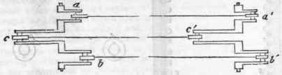
Motion is often required to be communicated to machinery at a distance from the first mover, and this is usually effected by a metallic shaft, which, if the distance between the machinery and the first mover be great, must be made of considerable thickness, to prevent its being twisted to pieces by the power applied, or else by chains, straps, or ropes, which, to prevent their slipping on the drums or pulleys over which they pass, causes considerable impediment to the motion by friction. These are inconveniences which cannot in all cases be avoided; but under some circumstances the following method of transmitting motion through the medium of three rods and two triple cranks, connecting the machinery with the first mover, might be introduced with considerable advantage. The apparatus is represented with the axes of motion placed horizontally by Fig. 1, and with the axes placed vertically by Fig. 2. The same letters represent similar parts in both figures. It will be perceived that the motion may be in the direction shown by the arrows, or the contrary; and hence it may be reversed at pleasure.
The triple crank a b c, to be put in rotation by any first mover, is connected by three rods to a similar crank a' b' c' of equal dimensions; and as the cranks project from the axes at equal distances, there will always be one of them in a position to produce a pulling action, and hence there will be no necessity for having the conducting rods stronger than what may be sufficient to sustain, by tension, the resistance of the machine to be put in motion, and thus the expense of transmitting motion by this method to a considerable distance will be very small. The motion, too, will be perfectly uniform; for as the leverage of the crank a, for instance, diminishes by its rotation, that of the corresponding crank a will be equally diminished; so that whatever motion is produced by the first mover will be faithfully transferred to the machinery.
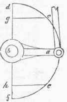
Fig.1.

Fig. 2.

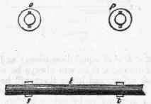
Fig. 3.
Fig. 1.
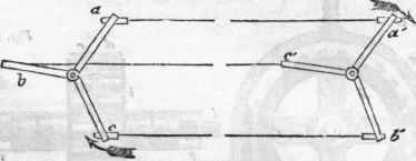
Fig. 2.
Continue to:
My Books

