Electric Telegraph. Part 2
Description
This section is from the book "The Engineer's And Mechanic's Encyclopaedia", by Luke Hebert. Also available from Amazon: Engineer's And Mechanic's Encyclopaedia.
Electric Telegraph. Part 2
Fig. 1.
We must now proceed to the description of the "Indicator," represented in Figures 2 and 3; Fig. 2 being an external elevation, and Fig. 3 showing the apparatus divested of the external casing.
Fig. 2.
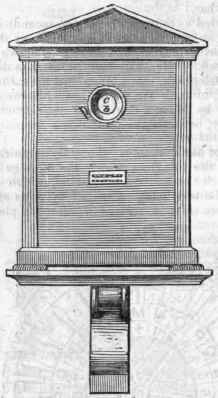
Fig. 3.
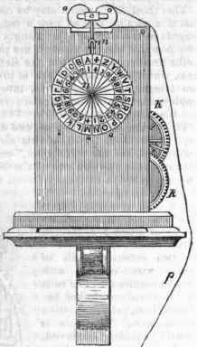
This instrument consists, in the first place, of a spring barrel and a train of wheels k, like a clock train, with a detent or escapement m, and having on the arbor of the last wheel a card n, marked with the letters of the alphabet, corresponding with those marked on the face of the communicator. Above the train, and opposite to an iron lever attached to the detent, is fixed a curved bar of soft iron, round which is wound a coil of covered wire o, which is connected by the wire p with the coils d d of the communicator; so that an electric current passing through the coils d d, passes at the same instant through the coil o; the iron bar then becomes instantly a powerful magnet, and attracting the lever releases the train, and allows the main arbor, with its card or dial plate, to revolve through the space of one division each time that the current passes through the wire. In the face of the casing which encloses the apparatus is cut an aperture q, (as shown in Fig. 3,) through which may be seen the uppermost letter and numeral on the dial card, and this card is so fixed on the arbor, that when any letter on the communicator is opposite to the pinion, that letter will stand uppermost on the dial, and appears through the aperture in the casing.
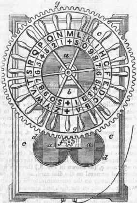
We will now suppose we wish to spell some word at the indicator, and suppose the communicator in the position shown in the drawing. Opposite the pinion of the communicator is the cross + and opposite to the hole in the indicator will also be the cross +. Let the word be "art": - if we turn the wheel of the communicator until the letter a is brought opposite the pinion, the coils will have rotated once, and a current running through the whole length of the wire, the wheel of the indicator will move through a tooth, and expose the letter a; we now turn the wheel until the letter r comes opposite the pinion, the coils will then be made to rotate as many times as there are letters between a and r, that is sixteen times, and sixteen currents will have passed through the wires, and the wheel of the indicator will have turned through sixteen teeth, and the letter r be exposed. We now want letter t, and the letter r being opposite the pinion, we have only to move the toothed wheel through the distance of two letters to bring t to the aperture in the indicator; by thus moving it, two currents pass along the wires, and the indicator wheel passes round through the distance of two teeth, and the letter t is presented.
It is obvious that in turning round the wheel of the communicator so as to bring opposite the pinion a distant letter, all the intermediate letters pass the pinion, and by the number of currents produced all the intermediate letters have passed before the opening in the indicator, but they pass so rapidly as not to be distinguishable, and no letter will rest opposite the hole but the proper one.
The telegraphic arrangement which we havejust described, although perhaps the most simple in principle, and the most readily comprehensible in its operation, is not that which is most generally employed in this country; being deemed, upon the whole, inferior to that arrangement whichis based upon the deflection of magnetic needles by the agency of electric currents, and which we shall now proceed to describe.
Fig. 1.
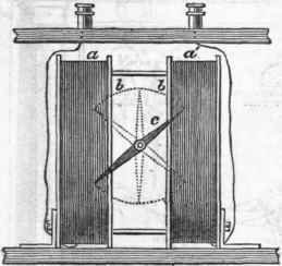
Fig. 2.
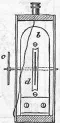
Fig. 1 and 2 represent the electro-magnetic portion of the apparatus, Fig. 1 being a front view, and Fig. 2 a transverse section, a & are two coils of covered wire wound round a brass frame b b, which is bolted to the bottom of the case in which the apparatus is concealed; c c are two magnetic needles fixed upon an axis d, which turns in bearings fixed to the back and front of the case. One of the needles is placed upon the middle of the axis between the coils of wire, slits d being formed in the frames b to admit of the vibration; the other needle is fixed upon the end of the axis, which projects beyond the face of the instrument. The needles are fixed upon the axis with their respective poles standing in opposite directions; that is to say, the north pole of the one needle, and the south pole of the other, points upwards, so as to counteract the effects of the dip of the needle. Upon passing an electric current through the coils, by connecting them with a galvanic battery, they immediately exert a deflective force upon the needles, attracting them to the right or left, according to the course of the electric current, which always flows from the positive to the "negative pole of the battery; thus, if the coil a be connected with the positive or silver pole of the battery, the upper end of the needle will point to the right; but if the coil a be connected with the positive pole, the needle will point to the left.
In the complete apparatus, two needles or pointers with their separate coils of wire are employed, and the letters of the alphabet, numerals, and a variety of conventional signals, are indicated by the single or combined movements of the needle on the face of a dial plate fixed in the front of the case in which the apparatus is enclosed, and which is shown in Fig. 3.
The indications of the various movements of the needles are as follows. The left hand needle moving once to the left indicates the +, which is given at the end of a word; twice in the same way, a; thrice, b; first right, then left, c; the reverse, d; once direct to the right, e; twice, f; thrice, a; and in the same order with the other needle for h, i, k, l, m, n, o, p.
Continue to:
My Books

