198. Straightening And Cutting To Length
Description
This section is from the book "An Elementary Outline Of Mechanical Processes", by G. W. Danforth. Also available from Amazon: An elementary outline of mechanical processes.
198. Straightening And Cutting To Length
After sizing, the tube is transferred to a machine which consists essentially of a pair of cross rolls as shown in Fig. 70. The axes of these rolls, BC and DG, are inclined at equal angles on each side of the tube axis KL. The tube is pushed through in the direction of its length between the two rolls, which revolve in the same direction.
The arrangement of these rolls is identical with that in the reeling machine. They are much longer than the reeling rolls. Their surfaces are hyperboloids of revolution and each face is generated by a straight line K'L' revolving about an axis B'C at a fixed distance OS from it. The two rolls are so inclined that the contact of the tube with the rolls approximates a generating element as near as possible.

Fig. 70. - Rolls for Straightening Tubes.
Suitable guides prevent the tube from taking any lateral movement.
From the straightening rolls, the tube is sent to the cooling table, down which it rolls gradually, against other tubes, to keep it straight as it cools.
The hot work on the tube is now complete, and without further operation than cutting to length and testing, these tubes are suitable for use as boiler tubes or for many mechanical and structural purposes.
After cutting to length in a simple cutting machine, each tube is tested to an internal hydrostatic pressure of 1000 lbs. per square inch, is carefully inspected and marked.
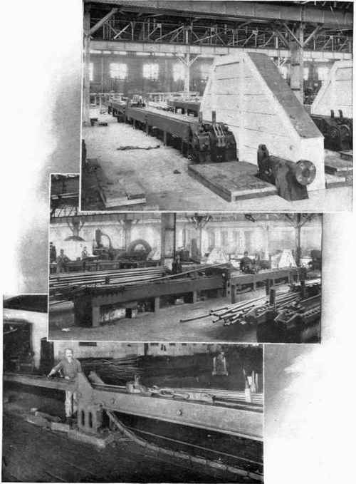
Fig. 71. - Three Views of a Cold-Draw Bench.
Annealing is not necessary, as the increase in its grain size is reduced by the constant working of the material after it left the furnace.
Continue to:
My Books

