Projects For The Living Room. Part 4
Description
This section is from the book "Do It Yourself With Aluminum. 125 Projects For The Home Craftsman", by G. W. Birdsall. Also available from Amazon: Do It Yourself With Aluminum.
Projects For The Living Room. Part 4
Prepare top-shelf ends (item 3) by drilling a 1" diameter hole 1" from rear end in both pieces; then drill a 1" hole 1094" from center of this hole for front leg. Use a 5° wedge block as in Fig. 4-57 to put this hole in line with the front legs .... all holes are 11/2"deepCut a 1/8"wide vertical slot 3/8"from back end and 1/4" deep for top-shelf back (item 1). Because there is a right and a left end piece, be sure to cut grooves on inside faces. Next cut a 3/4" groove 3/4" wide and bottom of piece for top shelf (item 2). Now taper from 31/2" height at back to 21/2" high at front by cutting off top edge.
Prepare item 2 by cutting a 1/8 wide groove 1/4" deep full length. Now round off front upper corner on upper side 3/8" in from back edge to receive item 1. Bevel front edge of this and all other shelves to a 5° angle to match slope of front legs.
Rabbet back edge of items 12 and 17, 5/8" wide, 1/8" deep to receive cabinet back, item 11.
Notch ends of items 6, 9, 12, and 17 to clear nuts. For "A" in Fig. 11-16, see detail in Fig. 474. Bend cabinet angle frames, item 13, per Fig. 4-39. Make first bend exactly 177/16" from end for the bottom corner and exactly 151/2" farther for the top corner bend. This will make the bottom piece 175/8" over all; front section, 157/8"; top section, 161/4".
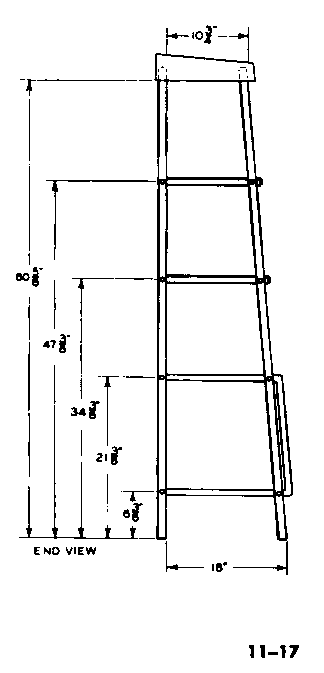
Start assembly operations by turning all four legs into upper-shelf ends, item 3. Lay out left end structure on the floor per Fig.11 -17, and drill holes through back leg at points indicated. Attach angle frame, item 13, to back leg, clamping together the members to be joined using C-clamps, then drilling and bolting. Indent holes for bolts per Fig. 4-73. Next position front leg, clamp, drill, and bolt. Use the same sequence in attaching shelf supports, items 7 and 10, being careful to square them up with the back leg before drilling and bolting to the front leg. Now lay out the other end of structure on the floor and assemble, remembering this is right-hand, the first one left-hand.
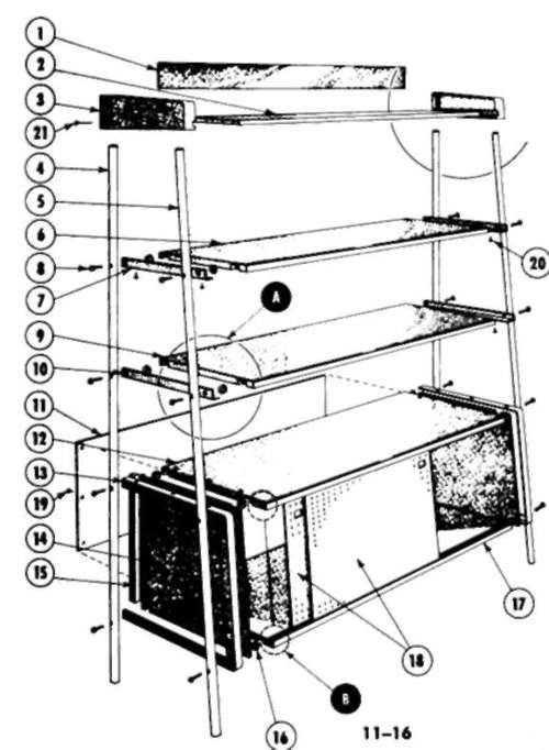
Now build up structure by attaching cabinet sides, item 14; the cabinet cleats, item 15; the cabinet bottom, item 17; cabinet top, item 12; shelf, item 9; shelf, item 6; and shelf, item 2. Put screws through item 13 up into bottom of item 17 first; then position all other members; now put screws up through item 7 into bottom of item 6. If the length of shelf members is not exactly right, make corrections at this point. Then put screws into shelves, items 9 and 12; attach cabinet back, item 13; and slip top shelf back into place.
Cut finger holes into the perforated Masonite sliding doors, paint them white, and assemble to cabinet. For brilliant aluminum finish, scrub with steel wool, sand with fine sandpaper, and apply wax or clear lacquer. Wood parts should be black enameled or lacquered after sealing.
If necessary, adjust leg lengths to make structure set square.
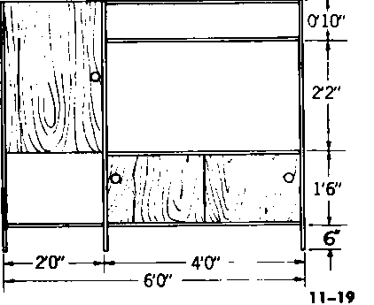
Thin Wall Divider (Fig. 11-18) is ideal where not too much space is available. Use 3/4" tube for legs. The back leg is 60" long, front slightly longer. Use 1/8" x 94" x 94" angle for framework.
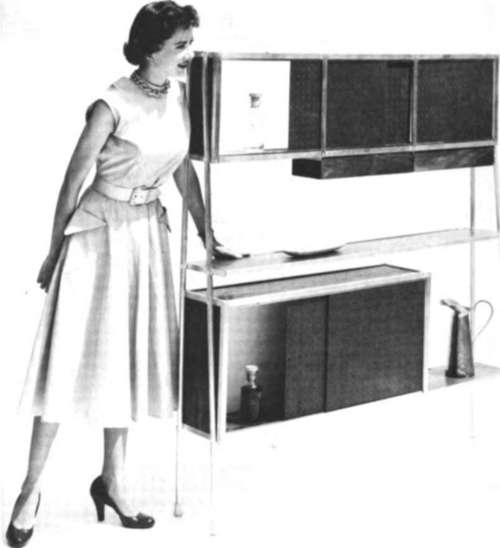
Fig. 11-18.
Start hy making box frame for upper cupboard 54" long, 14" high, 6" deep. Or you can omit the longitudinal aluminum members and use the 3/4" plywood top and bottom only. In either case, cut and attach end panels of 94 plywood to fit end frames.
Construct lower cabinet 36" long, 18" high, 9" deep, using 94" angle framing. Here again, only the left-hand end frame is absolutely necessary, the rest of the box section being self-supporting if made from 3/4" plywood. Note that cabinet bottom extends the full width of divider, 54" between leg members.
The full-length (54") shelf above lower cabinet is also 9" deep.
Slot upper and lower cabinet shelves to take sliding doors, per Fig. 4-82. Cut perforated Masonite panels to fit. Cut hack panels for both upper and lower cabinets, and assemble to cabinets. With both cabinets completed and finished (satin black is recommended ), place them face down on the floor.
Clamp back leg to lower cabinet so it will be 11" from floor (when upright). Drill lower bolt hole through tube and angle frame, indent per Fig. 4-73, and insert wood screw into cabinet. Drill, indent, and screw leg to upper portion of cabinet. Now clamp center shelf and its angle support to the back leg so bottom of shelf is 3" above top of lower cabinet. Then drill back leg and angle, indent, and insert wood screw at this point.
Now position top of upper cabinet even with upper end of leg, clamp, drill, indent, and insert wood screws in both top and bottom of this cabinet. Next attach the other back leg to opposite points on cabinets and shelves.
To position front leg, turn cabinets over with back to floor, clamp top of tube to the mid-point of top end-frame member of the top cabinet (4" from back). Drill through tube and angle, indent, and insert wood screw into cabinet. Now position bottom end of front leg so the inside distance between the front and back legs at the floor level is exactly 71/2". Clamp in this position, drill through tube and angle at bottom of lower cabinet, indent, and insert wood screw into cabinet. The front leg is now positioned so it can be attached to the lower member of the upper cabinet, to the shelf, and to the upper frame member of the lower cabinet. Be sure to position center shelf so it is square with back leg before attaching to front leg.
Continue to:
My Books

