Lanterns, Skylights, And Ventilators. Part 4
Description
This section is from the book "Notes On Construction In Mild Steel", by Henry Fidler. Also available from Amazon: Notes On Construction In Mild Steel.
Lanterns, Skylights, And Ventilators. Part 4
The riveted connection of the braces with the upper and lower members of the principal is shown in detail in Figs. 304, 305, 306, and 307, Fig. 304 showing the detail of connection of purlin to main rafter or upper member of principal. The purlins, which are of tee steels, are capped with a timber sill 4½" X 2", to which the roof boarding is nailed, and it may here be remarked that where boarding is to be attached to ironwork, two alternatives appear to present themselves as a general rule - either the ironwork is punched or drilled for screws to be attached directly to the boarding, in which case the pitch of the holes must be such as to agree with the width of the boards. This latter implies that the gauge of both holes and boards must be rigidly maintained, as, if one gains on the other, a screw will fall on a joint of the boards sooner or later, which leads to bad work. The maintenance of such accuracy becomes difficult in practice, and the other alternative method appears the better, being the construction shown in the figure. The timber sill is attached to the top table of the purlin by screws at a pitch which need not have greater accuracy than such work implies, while the boarding is nailed or screwed down, timber to timber, no particular maintenance of gauge of boarding widths being necessary.
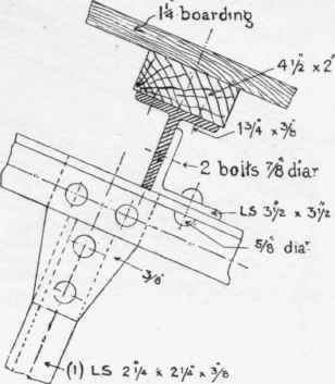
Fig. 304. Scale 1½ inch = 1 foot.

Fig. 305. Scale 1½ inch = 1 foot.

Fig. 306. Scale 1½ inch = 1 foot.
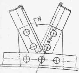
Fig. 307. Scale 1½ inch = 1 foot.

Fig. 308. Scale 1 inch = 20 feet.
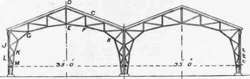
Fig. 309. Scale 1 inch = 20 feet.

Fig. 311. Scale 1½ inch = 1 foot.
Fig. 312. Scale 1½ inch = 1 foot.
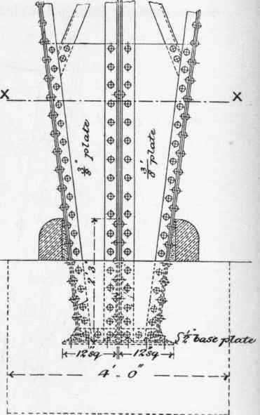
Fig. 313. Scale ½ inch = 1 foot.
Fig. 314. Scale ¾ inch = 1 foot.

Fig. 315. Scale 1½ inch = 1 foot.

Fig. 316. Scale 1½ inch = 1 foot.
Details of lantern and ventilator standards, with their attachments to rafters and purlins, and the junction of roof covering with ventilator details, are shown in Figs. 262, 264, and 265, 266.
The covering of this roof consists of slates on felt and boarding.
That class of structure which is represented by a series of roof principals supported on rows of vertical columns includes a multiplicity of examples applied to very diversified purposes, whether the structure be closed in or left open-sided and open-ended.
In this type of structure vertical loading is usually amply provided for, while the stresses due to horizontal wind pressure, or the horizontal components of that pressure, are resisted by the rows of columns, considered as vertical cantilevers, fixed at their bases.

Fig. 317. Scale 1½ inch = 1 foot.

Fig. 318. Scale 1½ inch = 1 foot.
This fixing of the base, including within that term the weight of the foundation to which the column is attached, together with the resistance of the attachments, holding-down bolts, or the like, frequently determines the ultimate resistance of the whole structure to overturning, and instances are not wanting where failure has occurred, under exceptional wind pressures, by reason of the overturning or pulling out of the ground of the foundation blocks to which the vertical standards or columns were attached.

Fig. 319 (Scale 1½ inch = 1 foot).
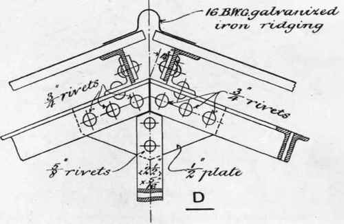
Fig. 320 (Scale 1½ inch a 1 foot).

FIG.321. Scale 1½ inch = 1 foot.
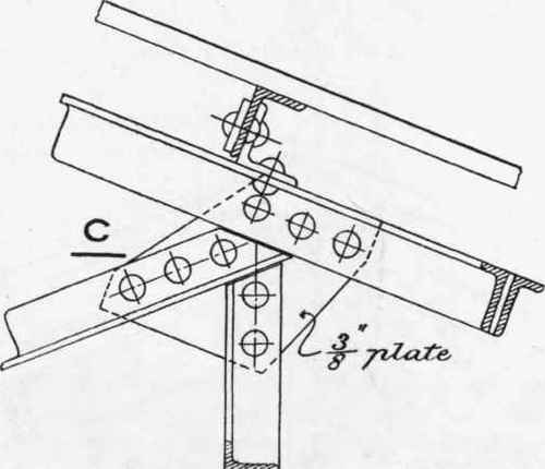
Fig. 322. Scale 1½ inch = 1 foot.
Considerations of this kind may occasionally lead to the employment in certain cases and in exposed situations of the types of roof principals represented in Fig. 308, where the roof principal is combined with the supporting columns in such a manner that the entire structure becomes virtually a rigid whole, capable of resisting satisfactorily the maximum horizontal wind pressures to which it can be exposed.

Fig. 323. Scale 1½ inch = 1 foot.

FIg. 324. Scale 1½ inch = 1 foot.
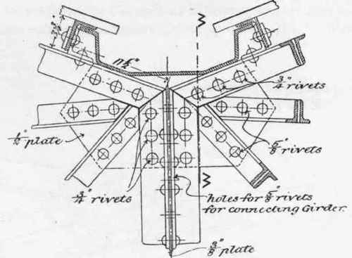
Fig. 325. (Scale 1 inch = 1 foot).

Fig. 326 (Scale ) inch = 1 foot).
This type has been successfully employed in numerous instances, ranging up to considerable spans. While not so well adapted to the reception of traveller girders or other lifting appliances as other types, it is very suitable for such structures as drill halls, concert halls, markets, and the like, the internal appearance of the curved ribs being satisfactory, if left exposed, or if ceiled the curvature of the lower members can be adjusted to the desired amount.
Fig. 327. Scale ⅜ inch = 1 foot.
The calculation of stresses due to combination of horizontal and vertical loads can be easily made by the usual methods of graphic analysis or by the method of sections, and it will be usually found that the weight required in foundation blocks is but slight, and the cost of foundations, in ordinary soils, will thereby be decreased.
The example here given is only of very moderate span, 35 feet, but the details will be treated somewhat fully, as affording guidance to the student in the design of a useful class of structure. As the purpose to which the building was applied did not require any enclosing walls, the sides and ends were left open, and as no roof lights or ventilators were consequently required, the roof covering details were of a very simple nature.
Fig. 328. Scale 1½ inch = 1 foot.
In Fig. 309, a pair of such structures is shown set back to back, forming a shed 70 feet wide in two spans. '
Continue to:
My Books

