Lanterns, Skylights, And Ventilators. Part 5
Description
This section is from the book "Notes On Construction In Mild Steel", by Henry Fidler. Also available from Amazon: Notes On Construction In Mild Steel.
Lanterns, Skylights, And Ventilators. Part 5
The method of securing the bases of the standards in their foundation blocks of concrete is shown in Figs. 310 and 311, in front and side elevation. To protect the standards from the blows of wheels of passing traffic, to which they are exposed, limestone curbs are placed, encircling the standards as shown in Figs. 310

Fig. 329. Scale 1½ inch = 1 foot.
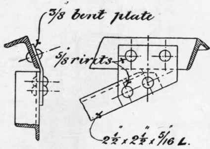
Fig. 330. Scale 1½ inch = 1 foot.
and 311, and in half plan in Fig. 312. The base of the standards is not provided with holding-down bolts in this case, as it is not capable of drawing out of the concrete block in which it is embedded, by reason of its shape. A sufficient thickness of concrete is left under the base to provide for vertical loading, to suit the conditions of soil on which the building is constructed.

Fig. 331. Scale l½inch = 1 foot.
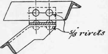
Fig. 332. Scale 1½ inch = 1 foot.
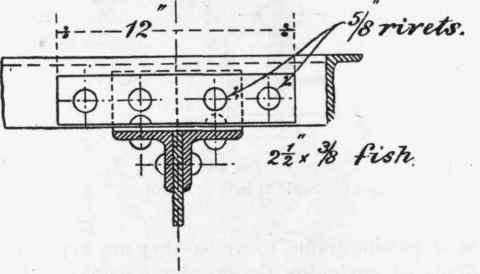
Fig. 333. Scale 1½ inch = 1 foot.

Fig. 334. Scale 1½ inch = 1 foot.
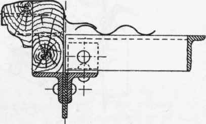
Fig. 335. Scale 1½ inch = 1 foot.
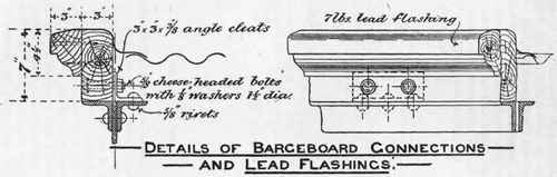
Fig. 336. Scale 1½ inch = 1 foot.
A similar foundation with limestone curb is shown, for the centre column of the double shed shown in Fig. 309, in Fig. 313. A sectional plan on line XX is shown in Fig. 314.
The upper and lower members of the roof truss are each formed of a pair of angle steels, spaced sufficiently far apart to admit the sketch plates which form the bracing connections. The objections to this form of construction from the point of view of the paint brush are pointed out in Chapter VII (The Protection Of Steel Surfaces From Corrosion)., but the convenience and fitness of the arrangement in other respects is shown by the details of connections which follow.

Fig. 337. Scale 1 inch = 1 foot.
Figs. 315 to 324 inclusive are details of the connections of the various points of junctions lettered in the figures, the same lettering being employed in Fig. 309.
Fig. 325 shows the detail of connections at the valley in the case of the pair of trusses placed back to back in Fig. 309.
It will be observed that a system of vertical members is introduced in the secondary bracing which affords facilities for the attachments of the struts to purlins. The purlins throughout the roof are of simple angle steel, but strutted in the manner shown in Figs. 326 and 327, the principals being 17 feet 3 inches apart centres.
Figs. 328 to 332 show the details of connections of the struts to the vertical members of the truss and to the angles forming the purlin bars, while the details at joints of purlin bars and their connection to the upper member of the truss are shown in Figs. 333, 334.

Fig. 338. Scale 1 inch = 1 foot.
Figs. 335, 336 show the connection of end of purlin bar to end principal, and also the details of the barge-board arrangement over end gable, with connection between the corrugated iron roof covering and lead flashing over barge-board.
The caps or heads of the standards at the roof eaves are all connected longitudinally by lattice girders 14 inches deep, carrying the eaves gutter as shown in Fig. 337, while the detail of the head of the standard prepared to receive the lattice girder is shown in Fig. 338.
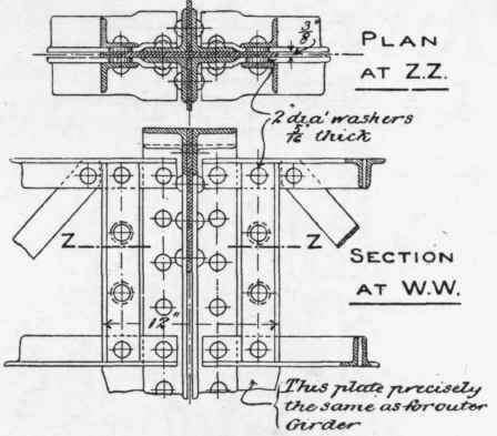
Similar details for the central lattice girder at the valley of the double shed shown in Fig. 309 are shown in Figs. 339 and 340, Fig. 340 being a section on the line WW shown in Fig. 325. Further details of the fascia and central girders are given in Figs. 341, 342.
A general cross-section of lattice fascia girder with eaves gutter resting upon it, and lowermost purlin bar, is given in Fig.
Figs. 339, 340. Scale 1 inch = 1 foot.
343, further details of eaves gutter and connections to lattice girder being shown in Figs. 252, 253.
The connections of eaves gutter to rain-water down-spout, and the mode of connection of the latter to framework of truss, are shown in Figs. 254 and 255.
Details of expansion joints, stopped ends, etc., of gutters are given in Figs. 256 to 260.
The detail of joint in valley gutter for double shed is shown in Fig. 257, while the method of attachment of valley gutter to the central lattice girder which carries it is shown in Fig. 258.
To ensure longitudinal stability in the entire length of shedding, certain bays were furnished with diagonal bracing (cruciform in arrangement) extending from the foot of one standard to the cap of the next. The attachment of bracing to the foot of a standard is shown in Fig. 344, and that to a cap of a standard in Fig. 326.
The covering of the roof was of galvanized corrugated sheet iron, attached to the purlin bars with hook bolts in the usual way.
The type above described is of course equally applicable to sheds with closed sides and ends, while provision can be made if required for skylights, ventilators, or roof glazing by the necessary modifications in detail of purlins, and attachments of skylight standards, etc., to the upper member of the truss.
Continue to:
My Books

