Purlins. Part 2
Description
This section is from the book "Notes On Construction In Mild Steel", by Henry Fidler. Also available from Amazon: Notes On Construction In Mild Steel.
Purlins. Part 2
The figures detailed in Table 35, and showing the average results of a considerable number of careful experiments on the rate of discharge of guttering, cesspools, and downpipes of a certain type of design, are therefore presented as a small contribution to the general subject, and are, of course, applicable only to the precise details described. They may serve perhaps to bring out some of the conditions with respect to flow and discharge which are to be met with in practice.

Fig. 246. Scale 1 inch = 1 foot.

Fig. 247. Scale 1 inch = 1 foot.
The gutter experimented upon is shown in Fig. 247, the flanged joints being partly internal and partly external, as shown in Fig. 248.
A similar section of gutter is shown in Fig. 250 with flanges wholly on the outside, as shown in Fig. 251. These flanges are machined, bolted, and made watertight with rust cement, the section of joint being of similar type to that in Fig. 257.
The connection of the normal run of gutter, with its cesspool, which occurs at a stopped end, is shown in Figs. 246 to 249.

Figs. 248, 249. Scale 1 inch = 1 foot.
Fig. 246 is a section on AB, and Fig. 247 a section on CD in Fig. 248.
It will be observed that the outlet and downpipe are arranged out of centre of the gutter, in order to clear the supporting lattice girder below, and the detail illustrates one of those practical conditions in the design of gutterwork to which purely hydraulic considerations have occasionally in some degree to give way. Fig. 248 is a plan, and Fig. 249 an elevation of the cesspool.
The actual section of valley gutter, with its cesspool and down-pipe forming one complete bay of roof drainage, was tested in position in the roof with the results detailed in the following table, the gutter being filled successively to the depths shown, and the contents allowed to discharge themselves freely through the apertures shown in the figures by the removal of suitably arranged plugs or valves.
Table No. 35. Table Showing The Results Of Experiments To Ascertain The Rate Of Discharge Of Rain-Water From The Gutter, Cesspool, And Downpipe Shown In Figs. 246 To 249
Internal diameter of downpipe in inches. | Fall in level of water in gutter. | Contents discharged in cubic inches. | Observed mean duration of flow in seconds. | Discharge in cubic inches per second. |
5 | 6" to 5" | 18,975 | 11.5 | 1650.0 |
5 | 5" to 4" | 18,975 | 265 | 716.0 |
5 | 4" to 3" | 18,975 | 37.0 | 512.8 |
5 | 3" to 2" | 18,975 | 66.5 | 285.3 |
5 | 6" to 2" | 75,900 | 141.5 | 536.4 |
The vertical length of downpipe attached to the cesspool in the above experiments was about 31 feet 6 inches to the junction with the rain-water drain, and was 5 inches internal diameter throughout. The necessities of design in arranging for the reception and attachment of the downpipe to a column of lattice construction, and in the passing of roof and traveller girders, gave rise to about 5 bends of 45 degrees each, so that the discharge was subject to conditions not more favourable than those usually found in practice.
The rapid decrease in discharge with the decrease of head over the mouth of the cesspool and downpipe will be observed, and the rate of decrease is greater than that due to theoretic loss of velocity following on loss of head. Probably the special conditions induced by the shape and dimensions of cesspool, the ratio of the area of the downpipe to the area of cesspool, and the inability of the volume and height of water contained in the cesspool over the mouth of the downpipe to maintain the latter in the condition of "full flow," are sufficient to account for the comparatively small discharge at low heads.
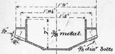
Fig. 250. Scale 1 inch = 1 foot.

Fig. 251. Scale 1 inch = 1 foot.
But these are conditions common in greater or less degree to most details of guttering and rain-water disposal, hence the value of practical experiment in cases such as the above - and a wide field is open for the student in the carrying out and analysis of experiments similar in kind, but covering a wider range of investigation into the influence of cross-section of gutter, the best form of cesspool, and the precise value of discharging power of varying diameters of downpipe.
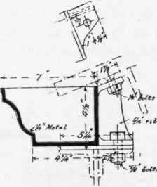
Fig. 252. Scale 1½ inch = 1 foot.

Fig. 253. Scale 1½ inch = 1 foot.
Continue to:
My Books

