Purlins. Part 3
Description
This section is from the book "Notes On Construction In Mild Steel", by Henry Fidler. Also available from Amazon: Notes On Construction In Mild Steel.
Purlins. Part 3
The arrangement indicated in the figures and experimented upon as described above, was intended for use in buildings of large area, with numerous valley gutters, and if an attempt were made to deduce from the above figures the maximum area of roof surface which could safely be drained by such an arrangement of gutter, cesspool, and downpipe, the calculation would include the following considerations. Assuming that no accidental obstruction occurs in the gutter or downpipe, such as collections of leaves, mud, etc., it will be desirable that the surface of water in the gutter shall never, during the period of heaviest rainfall, be allowed to stand higher than will give a certain margin of safety to prevent overflow and flooding, especially in those cases where such an occurrence would be attended with serious annoyance and discomfort. In estimating this margin, it will be necessary to remember that the surface of water in the gutter flowing towards the cesspool or outlet will not be level, but will assume an hydraulic gradient. In the experiments above described, and with the section of gutter shown in the figures, this gradient was found to be, in a length of about 106 feet, in the ratio of about 1 in 600.

Fig. 254. Scale 1½ inch = 1 foot.
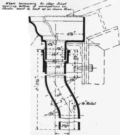
Fig. 255. Scale 1½ inch = 1 foot.
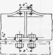
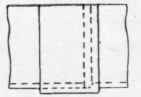
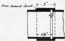
Fig. 256. Scale 1½ inch = 1 foot.

Fig. 257. Scale 1½ inch = 1 foot.
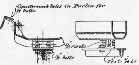
Fig. 258. Scale 1 inch = 1 foot.

Fig. 259. Scale 1¾ inch et 1 foot.


Fig. 260. Scale 1½ inch = 1 foot.
Allowing, then, for this gradient, and determining the desirable amount of margin below the lip of the gutter at the highest end of the flow, we can deduce the approximate head which will be available at the cesspool, and the corresponding discharge, which, as we have seen, will rapidly decrease with a diminishing head. The amount of discharge which can be relied on under these conditions can then be equated with the maximum rainfall per hour, or some still shorter period, and the area of roof which can be safely drained under the conditions assumed can thus be ascertained.
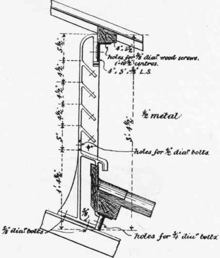
Fig. 261. Scale ¾ inch = 1 foot.
In the example quoted the actual area of roof drained was about 4945 square feet to one 5-inch downpipe, and it is calculated that, assuming a maximum and exceptional storm rainfall of about 2½ inches per hour, the highest level of water in the gutter would be about 3 inches below the edge, giving a margin of safety of 3 inches before the gutter brimmed over, thereby affording a possible increase of head under emergencies which would, from the experiments, be attended by a rapid increase in rate of discharge.
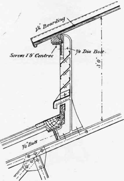
Fig. 262. Scale ¾ inch = 1 foot.
The above remarks apply to gutters of a constant section laid, as they frequently are, for simplicity of construction in details, dead level from end to cesspool. Gutters laid with drips and of varying cross-section fall under a different category.
Various forms of gutter with their attachments, both valley, eaves, and wall gutters, are illustrated in the figures which follow, but no attempt has been made in these notes to illustrate the numerous types of ornamental cast-iron guttering for architectural purposes which are to be found elaborately illustrated in the catalogues of art ironfounders, and many of which exhibit much beauty of design. The examples here given are purely utilitarian, and are such as would be found in stores, warehouses, station-roofs, and the like.
An eaves or fascia gutter with details of attachments and outlets is shown in Figs. 252 to 256 inclusive. Another type of valley gutter is shown in Figs. 251 and 258. A wall gutter is shown in Figs. 259 and 274, while in Fig. 272 is shown a wall gutter associated with a cast-iron tank forming portion of a roof covering, and further alluded to in Chapter III (Upon Certain Applications Of Riveted Girderwork, With Some Remarks Upon Rivets And Rivet-Holes)., p. 172.
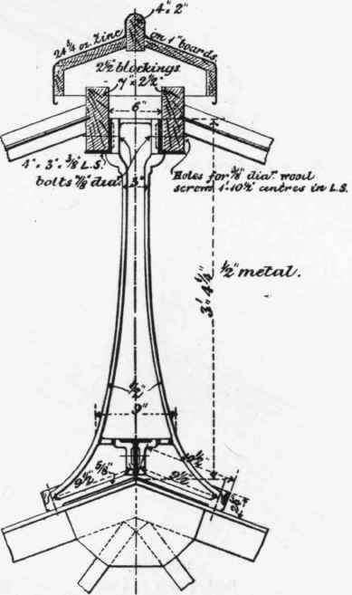
Fig. 263. Scale ¾ inch = 1 foot.
In long straight stretches of guttering, expansion joints should be introduced, and to avoid the difficulty of making such a joint thoroughly watertight, the expedient is frequently adopted of making the necessary provision for expansion by leaving a space between two stopped ends of gutter as shown in Fig. 260, and roofing over the space so left either with a lead capping as in Fig. 260, or by a cast-iron capping or saddle piece.

Fig. 264. Scale ¾ inch = 1 foot.
Such stopped ends must be considered as the summit levels, or parting of the waters, in the general system of drainage, and the down-spouts must be arranged accordingly.
Continue to:
My Books

