Chapter XVIII. Interchangeable Machine Parts
Description
This section is from the book "Machines And Tools Employed In The Working Of Sheet Metals", by R. B. Hodgson. Also available from Amazon: Machines and tools employed in the working of sheet metals.
Chapter XVIII. Interchangeable Machine Parts
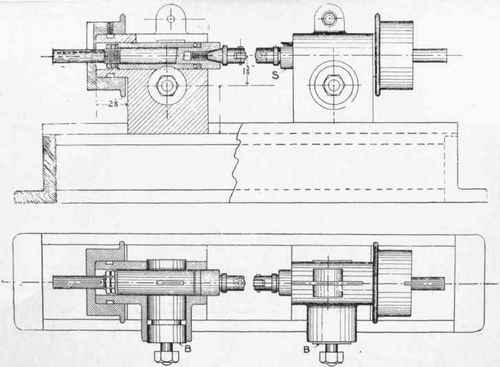
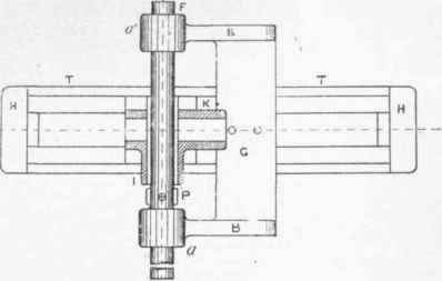
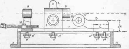
Machines of somewhat small and delicate design are frequently required in which their members must necessarily come together accurately and yet be interchangeable. A machine of this description is shown at fig. 246, as used for spinning the heads of rivets. A barrel B, having teeth formed upon a portion of its length, gears into a rack formed on the sleeve S, and as it rotates so the sleeve is advanced, carrying forward the spinning tools to operate upon the rivet head. Assuming that one dozen or more machines are to be made from this pattern, and that any pair of heads are expected to come together, and their centres to be in perfect alignment, and further that any barrel or any sleeve shall pass into and be a working fit in any one of the twenty-four or more headstocks, the work will necessarily be of a delicate nature, and it is essential that special care be taken in the boring of the headstocks. With the very best class of tools and first-class workmen, it is questionable whether the parts could be made interchangeable, unless jigs are used. It is, however, possible, in these special instances, to insure that the heads be bored so that the results are perfectly reliable if suitable jigs, which may be of simple design, are provided for the purpose. To trace how these twenty-four headstocks may be bored will demonstrate the principle of the jig as applied to this class of work. In fig. 247 the casting H is planed out to receive the base of the headstocks to be bored. At fig. 249 four castings, A, B, C, and D, are seen, two of which are prepared to receive the boring bar E. Taking, for example, castings A and B, their bases must be planed to fit the jig bed H, and they are next set out at the required height, and bored upon the angle and face-plates of an ordinary lathe. The next step is to fix them upon the casting H, fig. 247, and introduce the boring bar E, which must be held by two collars (not shown), so that the bar can rotate in castings A and B, but not move in the direction of its length. A and B may have been set out and bored by a careful and competent turner, but are not likely to be absolutely perfect. The next step is to bore C and D in the same manner that A and B were bored, only the holes in the former must be, say, 1/16 in. larger in diameter, to enable the boring bar to rotate freely without touching the casting?, whilst the bar is being carried by the smaller holes in A and B. The reason for this will be understood by referring to fig. 247, where C is to be bored. The castings C and D, in their turn, are placed upon bed H, and are held down by plates and pins, only sufficient pressure being given to ensure keeping them down upon the bed, but to allow of them being moved along the bed under the pressure from a long set-screw. It will be noticed that casting A has been drilled and tapped at M, to receive the screw F seen at fig. 251. This set-screw is placed in the boss, and brought up against boss M2 of casting C, thereby moving the latter along the bed to enable cutter O to bore the hole. From this it will be seen that, ever supposing A and B to have been inaccurately bored, C and D are certain to be accurate, if reasonable care has been taken to see that the bar runs a good fit in A and B. Castings A and B may be thrown away, since they will not be required again. The boring bar just used is now substituted by a larger boring bar E1. Fig. 248 shows headstock K being bored. This headstock K and all subsequent ones are, in their turn, moved along the casting by means of the long set-pin f, to enable the boring to be done. Another casting G, fig. 250, which is securely fastened to the bed H, carries the boring bar F, and forms a jig for boring the transverse hole to receive the barrel wheel B (seen at fig. 246). In this case the boring bar travels along carrying the cutter P, whilst the headstock K is firmly fixed to the bed H. A part section of the jig is shown at fig. 251. It will be necessary to drill and tap a hole in casting C at boss M2 to receive the set-pin. There may appear to be a fair amount of labour required in making this jig, but a careful study of its action will demonstrate that its value as a safeguard against inaccuracy will amply repay itself.

Fig. 246.

Fig. 247.

Fig. 248.

Fig. 249.


Fig. 251.
Continue to:


