Design For A Light Gasolene Car
Description
This section is from the book "Amateur Work Magazine Vol3". Also available from Amazon: Amateur Work.
Design For A Light Gasolene Car
J. C. Brocksmith. M. E.
Reprinted by Special Arrangement with the American Electrician.
The accompanying working drawings illustrate a type of gasolene automobile which is about as light and simple in construction as such a machine can be made consistent with the reach of the amateur builder and automobile enthusiast. The well-known arrangement of " motor in front, sliding gear transmission, and bevel gear drive" has been adopted as representing the best practice for light cars. Fig. 1 is a side elevation of the complete machine, which shows the general arrangement and appearance of the car.
The motor is a two-cylinder vertical machine of the two-stroke cycle type ; it is air cooled and located under a well ventilated bonnet in front. The motor has an output of 6 horse power at the normal speed of 750 r. p. m. The power is transmitted through a cone clutch in the fly-wheel to the transmission gear which provides forward speeds of 6, 12, and 25 miles an hour and one reverse speed of 6 miles an hour, all at the normal motor 6peed of 750 r. p. m. It will be understood, however, that any intermediate speed can be obtained by the usual methods of shifting the spark and throttle control. The rear axle is driven through a universal joint and bevel gear, the latter being enclosed in the same case which contains the differential gear.
Steering is effected by means of a hand-wheel operating a screw and nut and is of the " irreversable " type; that is, no inequalities in the road can work back through the steering linkage and produce a motion of the hand-wheel. Upon the steering column are also mounted the spark and throttle levers, by means of which the speed of the motor is controlled. The machine is further controlled by means of the clutch release and brake pedals which are seen protruding above the inclined footboard. The gear is changed by means of the lever shown alongside the seat on the right-hand side. When changing from one gear to the next the clutch pedal must, of course, first be depressed, thus disengaging the motor from the transmission, so that no power is passing through the gears and they can be brought into mesh without danger of stripping the teeth.
The brake acts on the secondary shaft of the change gear, and being geared up to the rear axle in the ratio of 4 to 1, a very powerful breaking effect is obtained with a moderate size of brake drum and a comparatively light pressure by the brake.
The gasolene tank is located directly under the seat and is filled through the cap shown in the top, which can be readily got at by removing the seat cushion.
The wood work of the seat is of the simplest possible description, only straight boards being used; the curved surfaces usually seen on automobile bodies would probably be out of the question for anyone who wished to construct the woodwork himself.
The body is hung on three springs, a semi-elliptic spring being used in front, while the rear springs are full elliptic. The wheels are 28 in. in diameter, have wooden spokes and are equipped with3-in. detachable pneumatic tires. Fig. 3 is an end elevation of the complete machine, which brings out a number of dimensions and points of construction not clearly indicated in Figs. 1 and 2. The front spring is a 38-in. 5-leaf semi-elliptic spring fastened at its extremities to a pair of short links to allow for extension, and at the centre is bolted to a wooden cross-bar which is shaped to fit the curvature of the spring and which supports the frame and body of the vehicle. The front axle is given a drop of 1 1/4 in. below the centre line of the wheels in order to give additional room for deflection of the springs and thus prevent the motor shaft from striking the axle.
This view also shows a section of one of the wheels, which brings out the construction of the hub and the form or the rim and tire, the latter two being of standard section and dimensions. The construction of the seat is also indicated in the view; it will be noted that the sides are inclined outwardly and come inside the flanges of the angle iron frame at the bottom, being fastened thereto by means of screws. The steering column is shown on the right-hand side of the machine, as this side is considered in common practice to be the best for operating the machine.
Fig. 2 shows a plan view of the chassis. This shows all the operating parts in their proper relation and is probably the be6t drawing to work from in assembling the machine. The frame is composed of two lengths of 2 in. x 2-in. x 3-16-in. angle steel, each 84 inches long. Across the front is bolted a piece of 2-in. ash which is shaped to fit the spring; 3/8-in. carriage bolts may be used for this, and a washer should be used under the nut to prevent it from cutting into the wood. Bolted to the under side of this cross-piece in front are two longitudinal frame members of 2-in. x 2-in. ash, to which the motor and change gear case are bolted. The rear ends of these longitudinal members are supported by, a 2-in. x2-in. cross-piece, which is in turn bolted to the bottom flanges of the angle-iron frame. The clutch release and brake pedals, it will be seen, are swung on rods attached to the wood frame members. The curved connecting link which moves the sliding gear shifter and connects with the hand lever
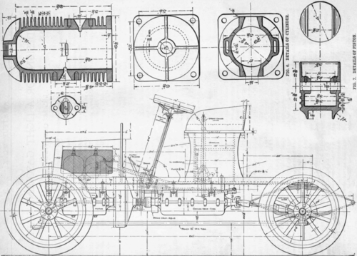
Fig. 1. Side Elevation Of Complete Machine is clearly indicated in this view. It is made of the peculiar shape shown in order to avoid interference with the frame members.
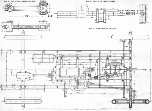
The exhaust pipe and muffler, which are represented as broken away in Fig. 1, are shown in position in this view. The exhaust pipe consists of a length of 1 1/2 in. steel tubing, bent to suit the frame members in front and fastened thereto by means of small clips of 1/8-in. x 1-in. iron. The muffler is simply a hollow sheet metal cylinder, with cast heads bolted in by means of a through bolt and perforated with numerous small holes on the under 6ide; the aggregate area of the perforations should be about equal to the area of the exhaust pipe in order to avoid undue back pressure. It is probable that a length of common 6 in. stove pipe will answer for the cylindrical part. If this is found to have an undesirable amount of resonance it may be wound with wire, which will stop the vibration of the walls and will also help to strengthen them. It will - probably be necessary to have a cross member in the frame at the extreme rear. The frame is left long in the rear to allow for the addition of tonneau seats if the builder finds them desirable.
Figs. 4 And 5. Front And Side Sections Of Motor

Fig. 3. End Elevation Of Complete Machine
The Motor
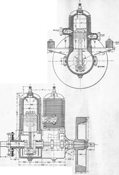
Fig. 4 is a front vertical section through the completed motor, which shows the location of the* various ports and passages. The motor has no valves and the pistons act as valves, opening and closing the inlet and exhaust ports in the usual manner of two-cycle motors. The cylinders are 4 in. bore by 4 in. stroke. The crank case is divided into halves along a horizon-taljdane and is of comparatively small diameter, the fly-wheel being placed outside. Arms are cast on the top half of the case by mean of which it is bolted to the frame of the car so as to afford proper clearance for the rotation of the fly-wheel. The pistons are long and have three rings for packing, which are made wider than the ports in the cylinder walls to avoid any liability to catching.
Both the inlet and the exhaust sides of the cylinder are provided with branch pipes; the connections for the main pipe in each case should be inclined to the axis of the cylinder, as shown in Fig. 5. The spark plugs are tapped into the centre of the cylinder head, where they are in a good- position to ignite the charge and also accessible for inspection and cleaning when this becomes necessary.
Fig. 5 is a semi-sectional side view of the complete motor. This shows the transfer passages connecting the cylinder with the crank case and also the shape of the deflecting vanes on the piston head. The contact maker is shown on the front bearing boss and is adapted to be rotated about the cam through a certain angle, thus varying the period of ignition in the customary way. The shaft is extended somewhat on this end for fitting on the starting crank.
Fig. 6 gives details of the cylinders; these should be cast of good close-grained gray iron, and the bore should be finished as smooth and true as possible. The cylinder wall is 5-16 in. thick and is provided with 23 cast flanges, 15-16 in. high, for cooling. The vertical section shows the size and proper location of the ports, the transfer ports being two in number i-\n. x 1 1/4 in. opening, and the Inlet and exhaust ports are each 15-16 x 2 ins.
Fig. 7 is a detail of the piston; it has three grooves turned for 3/8 in. rings. The rings should be about 1-64 in. larger than the bore of the cylinder and 1/8| in. thick. They are then cut through with a diagonal slot and should be fitted to the bore so that the ends stand a trifle apart to allow for expansion when they heat up during operation. The body of the piston should be turned about three one-thousandths small for the bore of the cylinder, and the grooves should be turned a nice fit for the rings, which can then be snapped into place and pinned to the piston so that the joints will not be required to traverse that portion of the cylinder which is broken by the ports. The wrist pin is 7/8|-in.cold rolled steel and is held in position by two 1/4-in. set screws in the inwardly projecting bosses.
Fig. 8 is a detail of the connecting rod. This is intended to be a phosphor-bronze casting. Provision is made at both ones for taking up water. Concl'd in Oct.
Continue to:
My Books

