Twist Drills. Their Uses And Abuses
Description
This section is from the book "Amateur Work Magazine Vol3". Also available from Amazon: Amateur Work.
Twist Drills. Their Uses And Abuses
By Courtesey of the Cleveland Twist Drill Company.
The advent of the now common twist drill marked a very important period in mechanical industry. It is, all things considered, the most efficient tool used by mechanics, as in no other tool is the cutting surface so large in proportion to the cross sectional area of the body or part which is its real support.
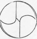
By actual measurement of the cross section of the fluted part only 50 per cent is left for effective work, yet it will bear more stress in proportion to its own strength than any tool, for the reason that it is supported by the metal upon which it is operating, and is thus prevented from springing away from its duty. This support may be of two kinds; first that due to the wedge-like action of the point, and the second that derived from the small amount of concentricity which the drill has just behind the cutting edges, see Fig. 1.
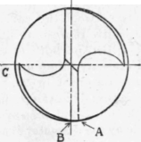
Fig-1.
The latter, however, is of little importance, as in a large number of cases only one side of the drill gives any support to the cutting edges, as will be seen in paragraph under grinding of points.
The support given the drill in the instance first cited is of more importance and arises from the tendeney of either cutting edge to spring away from the cut, which in a correctly ground drill is, of course, counterbalanced by the opposite cutting edge having the same tendency, only in an opposite direction, so that with the feed pressure on the drill tending to force the cone shaped point into a cone shaped hole, the drill is held rigidly in a central position.
A twist drill is a tool generally formed by milling or forging two equal and opposite spiral grooves upon a cylindrical piece of tool steel of such shape as to make a suitable cutting edge on its cone shaped end.
Drills are not of the same diameter from end to end of the twist, but decrease in diameter from the point towards the shank by an amount varying from .00025 to .0015 per inch in length, according to the size or particular use for which they are intended. This gives a longitudinal relief to the drill which is very essential in accurate drilling.
Neither are they exactly round, as their diameter is eased away from a short distance behind the cutting edge back to the flute, as in Fig. 1. The distance between A and B is of full diameter and round, while from'B to C it is eccentric or, more strictly, is a surface whose cross section is a spiral with its centre in the centre of the drill. This is called body clearance. The object of this is to give radial clearance to the drill and thereby reduce the friction between the drill and the walls of the hole. Without this body clearance more power would be required to turn it and in some cases enough heat would be generated to draw the temper in the drill to a degree which would unfit it for further use.
To give the drills as much strength as possible the flutes decrease in depth toward the shank, that is the "web" between them gradually increases in thickness toward the shank ; this is accomplished by gradually withdrawing the milling cutters as they approach the shank, and is called web increase.
This operation alone would seriously impair the chip room in the tool, and to avoid this defect the spiral is increased in pitch by an amount that, combined with the web increase, will preserve the correct and equal cross sectional area of the flute from point to shank.
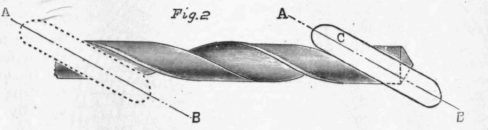
This is made plain by reference to Fig. 2 in which the cutter Cis in position at the point of the drill with its path on line AB. As the blank is fed uniformly forward it revolves at a rate which is constantly diminishing, and as the axis of the cutter remains in a fixed angular relation to the axis of the drill, it is obvious that the flute will be wider at the shank end th»n at the point, and at the completion of the groove the cutter will be in position shown by dotted lines; but as the cutter is gradually withdrawn in depth the combination of these two movements retains the proper volume of the flute for free egress of chips.
With a special apparatus for making an autographic record or diagram of both the feed pressure and the torsional stress when forcing a drill through a piece of metal, we performed experiments which showed the most efficient form of point, manner of grinding, etc.
We replaced the usual swing table of a drill press by a special hydraulic one arranged so that the exact feed pressure and torsional stress was measured and recorded by two Bristol Pressure Gages, the clock mechanisms of which were removed and a spring drum substituted by which the vertical movements of the drill spindle revolved the charts.
The charts shown are from a 1± in. drill, running 66 revolutions a minute with a feed of .0075 in cast iron, machinery steel and annealed tool steel. The concentric circle on feed pressure chart between lines reading 10 and 20 represents the weight of table and "billet" drilled into. The lines marked 1 are cast iron and show quite a uniform curve, while the lines marked 2 and 3 are respectively machinery steel and tool steel, and show more irregularity in the curves.
Fig. 3..
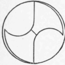
Fig.4
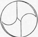
Fig.5.
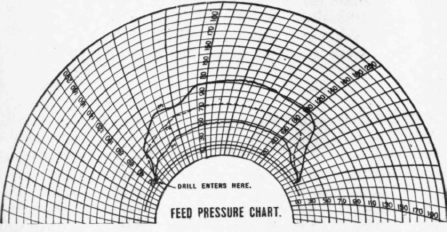

The general contours of the feed pressure curves for tool steel are very much alike, showing a steady rise until the lips are cutting nearly full size, then dropping slightly, due to the spiral helping to pull the drill in, then rising again steadily to a point about a third through the billet, due no doubt to the billet not being annealed uniformly clear through.
The feed pressure diagrams fall off very rapidly as the point begins to come through, while the tension diagrams for steel rise very abruptly; and the tool steel one (the piece not being clamped down) shows plainly where the lips caught and raised the piece, giving several very quick jerks, a result which is experienced very often when holding a piece by hand to drill it.
These points indicate where the outer parts of the lips are generally broken, especially where lever feeds are used, or the spring berween the parts taking thrust is considerable. This feature is very common in the drilling of the rivet holes in cylindrical shells where the inside curvature greatly augments the tendency of the drill to " hog in."
The feed in this test was purposely kept down to
Fig. 6.
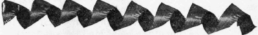
Fig. 7.
what may be termed fair practice in order to have the same grinding answer for all three holes. The difference between the curved lines pointing toward the centre represents a distance of .05 inch in depth drilled on both charts. To find the actual feed pressure in pounds multiply the indicated pressure on chart by 20. To find the torsional stress in pounds at the periphery of the drill, multiply the indicated pressure on the chart by 20 and divide by the diameter of the drill. We found the shape of groove, the angle of point, the angle of spiral and the manner of grinding all affected the power needed to drill a given hole. The thickness of web also affected the result, but this is probably the most uniform feature on the different makes of drills, and varies but slightly.
A groove formed like Fig. 2 required the most power, while those like Figs. 4 and 5 gave the best results. A little study of Fig. 3 will show that the cutting edges are very poorly formed, especially toward the cutter where there is very little of the shape which will allow free curl to the chips. Fig. 4 represents a very free cutting I drill; the shape of the groove is such that the chip curls up to the full size of the groove and very little power is consumed in feeding it. The form of the chip is very similar to an open string wound with ribbon steel, and somewhat resembles a cylinder in appearance, see Fig. 6. Fig 5 represents a form of point very desirable for several reasons and is the shape which we have adopted. It does not require any morepowcr (in fact slightlo less) than the point like Fig 4, and rolls a beautiful chip (see Fig. 7) of which each turn is slightly conical in shape, slightly less in diameter than that of Fig. 6, but they lie one within another so that the length of clip in drilling a hole one inch deep is not a quarter as long as that made by a point like Fig. 4 drilling the same depth.
Our tests with different angles of points showed that the feed pressure varied almost directly with the number of degrees in the included angle of the point between 110° and 136°. Different materials gave somewhat different results, the variation being not so great in the harder materials.
Continue to:
My Books

