100watt Transformer
Description
This section is from the book "Amateur Work Magazine Vol4". Also available from Amazon: Amateur Work.
100watt Transformer
R. G. Griswold.
The transformer described in this article is intended for amateur construction and amateur experimentation. The materials are such that they may be readily obtained, and the entire piece of apparatus requires a very small outlay.
The capacity of the transformer is approximately 100 watts, and is designed for transforming from 100 volts to 10 volts on 125 cycles. This voltage is a very convenient one for light experimental work, and the instrument is so designed that several different coils may be wound and placed on the same core, as it is made in removable sections. The secondary is also tapped in five places, thus making it possible to obtain different voltages from the single winding.
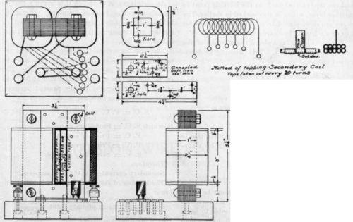
The core of the magnets is lami-nated,or built up of strips of soft iron 1 in. wide by about .015 in. or .020 in. thick, and of the lengths given in the drawing. These strips are laid up, one on top of the other, until a pile 1 in. thick is built up. The strips are placed directly on top of each other, but with one end of one lapping over the lower one by 1 in, the next one lapping over by a similar space at the opposite end. This provides the ends of each section with a series of tongues and slots, which will slip into a similar arrangement on the next section. This makes a very good magnetic joint, and the several ends are clamped firmly in contact by the 1/4 in. bolt running through as shown. This arrangement affords the shortest possible magnetic circuit, and also permits an interchange of coils for other experiments or voltages and outputs.
When the pieces are properly laid, one on top of the other, as directed, they are riveted together by three 1/8 in. rivets, as indicated. The four pieces are then bolted together and the ends finished off smoothly with a knife. Then place the four pieces, either bolted together or separate, in a fire and heat to a dull red for an hour. Remove after one hour and allow them to cool very slowly by burying in ashes. This anneals the iron and, while it is not absolutely essential, it is advisable to do so, as the magnetic qualities of the iron are benefited by the treatment.
The fibre washers are now forced into place. Next, wrap the two cores holding the magnet coils with cotton tape (1/2 in. wide) beginning close up against the fibre heads. The tape should half lap over itself on each turn, so that there may be no spots left bare. When the first layer is finished it is thoroughly soaked with shellac varnish and the tape carried back to the starting point in another layer, which is also soaked in shellac. The cores are now placed in an oven and baked for five or six hours, thus hardening the shellac.
The cores being completed the winding of the primary coil is begun. This winding is determined from the formula
B N F E. M. F.=4.44 100,000,000 in which
E. M. F.=electro-motive force in volts.
B=magnetic flux in lines per square in.
N=number of turns in winding.
F=:frequency of cycles.
Since it is the number of turns required that is to be determined, we can solve for N by transposing
N=100,000,000 E. M. F. 4.44 B F
The frequency is generally known and in this case is 125. The magnetic flux must be taken with regard to the cross section of the core, and with this frequency it is not advisable to use a magnetic density in the core much higher than 20,000 lines per square inch. Owing to the laminated structure of our cores we can hardly count on more than 90 per cent of the total cross section, as there is always a slight space between the strips. Counting on 9 square in. the total magnetic flux through the core will be 20,000 X.9=
18,000 lines. Assuming the primary voltage to be 100, we have
N= 4.44X18,000X125/100,000,000X100=1,000 turns approximate.
For an output of 100 watts, neglecting the losses and magnetizing current, the primary current would be109/100=l ampere, and in order to prevent overheating in the coils, the primary should have a cross-sectional area of 1000 circular mills per ampere. No. 20 B. & S. wire has an area of 1021 circular mills, so that this wire is used. This wire should be double cotton covered, which gives it an outside diameter of about .040 in. and about 25 turns can be wound per inch of core length. As each coil is to contain about 500 turns, and each layer will take 75 turns, it will require 6.6 layers to contain the number of turns, but since even layers are desirable, the last layer will be finished, making 7 layers and about 525 turns.
As each layer is wound on it is given a coat of shellac and the finished winding thoroughly baked. Then three layers of linen soaked in shellac are wrapped over the primary coil and baked until dry.
The next operation requiring attention is the secondary coil. The secondary voltage is to be 10 volts with a primary voltage of 100. The secondary current of this transformer at full load is found close enough for the present purposes from the following formula:
S.C=P.C X P. V./S.V.
in which S. C. = Secondary current. P. C. = Primary current. P. V. = Primary voltage. S. V. = Secondary voltage. Therefore
Secondary current=1X100/10 amperes. The number of secondary turns is found as follows:
Secondary turns = primary turns XS.V/P.V>
Hence for this transformer,
Secondary turns=1000=10/100.
Allowing 1000 circular mills per ampere, this secondary will require a cross section of 10,000 mills, which is very nearly covered by a No. 10 B. & S. wire. The 100 turns will be equally divided between the two coils, or 50 turns to each, which can be wound on in two layers. These layers are also shellacked and baked after placing the taps in as shown.
These taps are made of thin copper, about No. 24 B. & S. guage and 1/2 in wide. They are soldered to the primary coil on every twentieth turn, as shown in the drawing. The taps from the lower layers are brought out between the turns of the upper layer, and the leads to the switch points on the base are soldered to the protruding ends.
The arrangement of switch and binding posts on the base may be altered to suit the the requirements of the user, so no special instructions are necessary on this point; the base is made of a block of some hard wood and, as far as possible, all connections should be made beneath the base, as shown. Two 3/8 in. screws should pass through the base into the lower segment of the magnet to secure it.
If the transformer is operated on 60 cycles instead of 125, the effect will be to increase the heating somewhat, but if the iron is of good quality the heating will not be large because the low density of 20,000 lines per square inch was assured. The no load current taken by the primary will be increased because a greater magnetizing force will be required to set up the magnetic flux. This will tend to increase the heating in the primary coil. The net result, therefore, of operating the transformer on 60 cycles would be to make it run somewhat warmer. Owing, however, to the intermittent load usually used in experimental work, the transformer should not run very warm. The secondary voltage would not be affected by a change in the frequency so long as the primary voltage and the ratio of primary voltage to secondary turns are not altered.
Owing to the construction of the core, the latitude of voltages of output may be easily varied by winding separate coils to slip over the cores, mounting the fibre heads on a square-formed tube of thin sheet iron.
If the primary is to be wound for 50 volts and the secondary for 10 volts, use 240 turns of No. 17 B. & S. on the primary and the same winding on the secondary, as below.
For a primary voltage of 100 and a secondary voltage of 5 with an amperage of 20, use the same winding as before for the primary and 25 turns of two No. 10 wires in parallel for the secondary on each spool.
The small transformer will be found useful for a number of purposes, especially if it is used in connection with a small rheostat by means of which the secondary current may be regulated. For operating miniature lamps, supplying current for operating small alternating-current motors or, in fact, for any purpose where a small alternating current at low voltage is required, it will be found very convenient. It is specially handy for experiments illustrating the heating effects of the electric current; it will fuse a considerable length of No. 18 wire without difficulty.
If a 5 volt secondary winding is used and taps brought out every 5 turns, it makes a good appliance for heating the cautery knives used in surgical work. The five volt secondary with taps every 5 turns, gives 10 steps of 1/2 volt each, which is close enough adjustment for most work.
Continue to:
My Books

