Foot Motion For Bench Lathe
Description
This section is from the book "Amateur Work Magazine Vol4". Also available from Amazon: Amateur Work.
Foot Motion For Bench Lathe
Frederick A. Draper
The amateur who possesses a bench lathe does not always find it convenient to operate it by power and is obliged to either purchase or make a foot motion for driving it. Those who prefer to make one will find the design here described easily made with but little machine work, and this can be done by any blacksmith possessing a drill, or by a machinist, as it consists only of the drilling of a few holes and threading some of them. The dimensions are suitable for the Amateur Lathe.
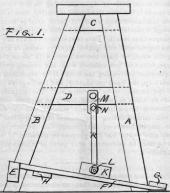
The wooden frame, shown in Fig. 1, is made of 2x 3 in. spruce, and when planed on all sides will measure l 3/4 X 2 3/4 in. The two pieces, A, are 30 in. long before the ends are cut to the angles to fit square on the floor, and to the top. The outer edges are distant from the vertical line of the driving shape, at the top 4 in. and at the bottom 9 in. The two pieces, B, are 32 in. long, and distant from the shaft line, at the top 4 in. and the bottom 15 in. The object in throwing out the bottom of these pieces is to give a longer treadle arm, thus securing a shorter throw, in this case 8 inches.
The two pieces, C, at the top are 9 1/2 in. long before cutting to the angles of the legs. They are mortised into the legs, care being used to get them to fit well, as poor fits will mean a wobbly frame. The pieces, D, are 16 in. long, also mortised to the legs with the upper edge 12 1/2 in. from the top of C.
The legs, when framed up as above are 24 1/2 in. apart, and as the piece, E, projects beyond them 3 in. at each end, this piece is 34 in. long. It is halved into the legs with the top edge 4$ in. from the floor. Note that it is also at an angle with the pieces, B, which is to avoid cutting out more than is necessary to make a firm joint. This piece is attached to the legs, B, with large wood screws, countersinking the heads.
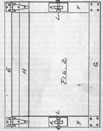
The treadle frame is shown in Fig. 2 and is made of selected spruce or oak, $ in. thick. The former is the more desirable, making a lighter frame. The two pieces, F, are 24 in. long and 3 in. wide. The p'iece, G is 34 in. long and 3 in. wide. It should be firmly attached to the outer ends of the pieces, F, with several wood screws, countersinking the heads. The piece, H, is 34 X 2 1/2 in. and fastened to the under sides of the pieces, F, with screws, the inner edge being spaced 1 in. from the ends of F.
Two pieces, K, of 2x3 spruce 5 in. long are fastened to the upper sides of the pieces, after cutting out holes for the treadle rods, R, Fig. 1. Long wood screws or bolts are used for fastening these pieces, as all the pull of the treadle comes upon them, and they should be well secured. Holes are bored through the centers of these pieces for the bolts, L, holding the treadle rod. These bolts are 3 x 1/2 in., square holes for the heads being cut on the inner sides of the blocksThe treadle frame when finished is attached to the piece, E, by two heavy tee hinges, which should be carefully placed so they will work without binding. The top is a piece of spruce plank 12 in. wide and 36 in. long attached to the frame with strong screws.
The shaft is 31 in. long and 1 in. diameter. This can be obtained of any dealer in shafting and will need no machine work. At the ends are two arms, M, 4 in. long and 2 in. wide and | in. thick, made from bar iron or steel. A 1 in. hole is drilled at one end and a | in. hole at the other, the centers being 2 in. apart. The smaller hole is tapped for a 1 x 1/2 in. machine bolt, N. After fitting the arms to the shaft, drill 1/4 in. holes and taper out with a taper reamer for a taper pin to key the arms to the shaft. Or a keyway may be cut with a cold chisel on the shaft, and a slot in the arm and a key fitted. Before finally fastening the arms in place, the drive wheel, W, is fitted to the shaft and also keyed in place.
The drive wheel is located just inside the left legs. Holes must also be bored in the cross pieces, D, to receive the shaft. These holes should be large enough to receive a bushing of brass or drawn steel tubing with a drive fit, the size of the hole depending on the thickness of tubing used. The drive wheel can be made of two thicknesses of 1 in. board, fastened together with glue and screws, and with the grain of each layer crossed, or can be of iron, if one can be purchased with the steps spaced correctly for the lathe.
The treadle rods, R, are made of bar iron or steel, and are 12 1/2 in. long, 1 1/4 in. wide and 3/8 in. thick. Holes are bored at each end for the studs, N, and bolts, L, the centers being 11 in. apart. The holes should have easy fits. The top hole can also be made 1 1/2 in. Ion by drilling two more holes below the first one and fil. ing out between. This will allow the treadle to lift should the foot be accidentally placed under it, and thus save being squeezed, as the treadle almost touches the floor. Anyone who has had a toe nipped with a treadle in this way will readily appreciate the value of having these Blots. No mention has been made of oil holes as, if the lathe is used but little, oiling can be done from the sides of the bearings. It is advisable, however, to drill holes down through the pieces, D, and the bearings, so that the shaft can be oiled.
The reader is also cautioned to see that the drive wheel is fitted to the shaft with the steps the right way to receive the belt. As the weight of the treadle will cause the drive wheel to come to rest with the treadle down, a counter weight can be riveted to the wheel to balance the treadle and prevent this back motion, which on some work might prove bothersome.
Continue to:
My Books

