Elements Of Dynamo Design. IV. Transforming; Alternations to give Direct Current in Circuit
Description
This section is from the book "Amateur Work Magazine Vol6". Also available from Amazon: Amateur Work.
Elements Of Dynamo Design. IV. Transforming; Alternations to give Direct Current in Circuit
Ira M. Cushing
The next step should be a consideration of the alternating E. M. F. impressed on circuit F from the rings and brushes, R and T in Fig. 10. A little though would clearly show that the rate of change of the lines going through the coil W vary much during a half revolution.
are shown the degrees which the coil passes through in a complete turn; namely 360. Vertical lines, erected from the base line indicate the values of the E. M. F. found at each degree, those above the base- line being considered as positive and those below as negative.

With the coil at right angles to the lines of force, as shown in the figure, a turn of a number of degrees makes but the slightest change in the lines threading through the coil. The E. M. F. is, therefore, at zero with the coil at 90 degrees to the lines, but begins "building up as the coil progresses in the turn until it
Through the points thus obtained draw a smooth curve, and the result will be the curve A C D E F. This shows, graphically, that the voltage is zero at 0, 180 and 360 degrees and maximum at 90 and 270 degrees. Since the coil has completed a revolution and is ready to start on another at the 360th degree, it can be


Fig. 13.
reaches the maximum when the coil is parallel to the lines of force, for at that point the rate of change is the greatest. As the coil continues it revolutions, the E. M. F. dies down again to zero, which is at the time the coil reaches the 180 degree mark. As the coil completes its turn the rise and fall of the E. M. F. is repeated, but in the opposite or negative direction.
The action can best be shown by diagrams. Let the line A-B, Fig. 12, represent zero potential. On this line readily seen that the curve repeats itself every 360 electrical degrees.
In the cycle described A C D is an alternator, and since D. E. F. is a duplicate of A C D, is except for the sign, it is seen that there are two alterations per cycle. The term electrical degrees is used because if the dynamo has more than two poles this cycle is repeated two or more times during a revolution; in fact, it is repeated as many times as there are pairs of poles, or in other words there are as many times 360 electrical degrees in an armature as there are pairs of poles.
As stated before, the object of the commutator was to reverse the E. M. F. delivered to the circuit at the same moment it was reversed in the armature. Its effect on the curve, or wave form as it is called, would be to reverse D E F, Fig. 12, into the dotted curve D G F. There will be then a series of positive impulses like A C D delivered to the circuit D. Fig. 10, producing a pulsating E. M. F. as distinguished from the alternating E. M. F. delivered to circuit F. These are called "sine waves" because they approach or approximate the curve called the "curve of sines."
The pulsating E. M. F. is not steady enough for our present electrical apparatus. A sensitive voltmeter taps brought to the segments of the commutator from equidistant points in the coil. This is true of all simple wound armatures, no matter how many segments the commutator has, and it is also the principle upon which all armatures of the drum type are wound.
It would be well now to study the effect of splitting the coil on the E. M. F. generated. Fig. 12 gives the rectified E. M. F. for the one coil. By halving the coil it is evident that the E. M. F. will be one half. As the second coil is 90 degrees away, its E. M. F. will, therefore, be 90 degrees away, starting at D, Fig. 14. Now, although the maximum voltage B D would be only one half of C J, Fig. 12, the average voltage M N, and represented by the line H K, would be the same as the voltage K D and the line H N of Fig. 12.
From this can be deduced that the output of the
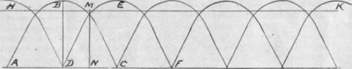
Fig. 14.
would vibrate so much that it would be almost impossible to obtain a reading. A sluggish voltmeter or, if the frequency was high an ordinary voltmeter, would read an average value of voltage between zero and the maximum value represented by C J. This average would be the line H K M N. One great disadvantage of the single coil in the armature is that the receiving apparatus must be insulated for a voltage equal to C J, while the working voltage is only K D.
The method of duplicating coils on the armature, as shown in a, Fig. 13, also has many disadvantages. It is readily seen that as the second coil is set at 90 degrees to the first its rise and fall of E. M. F. will come 90 degrees behind that of the first and will therefore help fill up the gap between the pulsations in the first coil. The one great trouble with this method of winding is that it is impossible to set the brushes on the neutral point; that is, the point on the commutator which is at the moment connected to the coil in which the voltage is changing. For this reason a heavy, distructive spark occurs between the brushes and the commutator segments as the brushes leave them.
Another way of winding which gives much better results, is shown at v, Fig. 13. This method is as if the original coil had been divided into two equal parts and one half turned through an angle of 90 degrees. The commutator, is also eut into two more segments and the taps from the new coil brought down to them. This winding is quite different from the first in a number of ways. It will be noticed that there is a continuous path through the coil all around the armature. This shows that the winding is really one big coil with armature would be the same whether it be wound in one big coil with a two segment commutator, or whether it is wound as many coils with as many segment commutator. The effect of increasing the coils is to reduce the voltage per coil (B D in Fig. 14) until it becomes approximately the same as M N, the average voltage of all the coils. It can be easily seen that multiplication of the wave curves A B C a few degrees apart would give nearly a straight line composed of just the wave tops.
Continue to:
My Books

