Practical Hints About Arc Lights
Description
This section is from the book "Amateur Work Magazine Vol6". Also available from Amazon: Amateur Work.
Practical Hints About Arc Lights
To the practical man, the history and theory of the are lamp are not a necessity, but the knowledge of its mechanism and mode of operation are absolutely essential. So long as the lamp needs only trimming and cleaning, the average attendant will ignore its mechanism, and in all probability no attempt will be made to comprehend its operation. The moment the lamp fails to light, strenuous efforts will be put forth to try to discover the reason for such failure.
When the lamp fails to light, assuming that it has been properly trimmed, one or all of the following causes may be looked for: 1st, the resistance coil may be burnt out; 2nd,the magnet coils may be burnt out; 3d, the framework may be grounded, thereby preventing sufficient current to flow through the carbons to produce an arc; 4th, broken or grounded connections; 5th, when the movable carbon is continually in motion, thus preventing a steady light; sth, when the clutch, fails to lift the carbon. These six difficulties will be the principal ones met with in practice.
The mechanism of an arc lamp is shown in Fig. 1, and while the shape and construction may vary with different manufacturers, the underlying principles involved in its operation will be found practically the same. Some lamps have their resistance coils wound on separate spools, others have no spools, while still •there have their resistance coils wound on one large spool. Again, some lamps are fitted with two magnet coils, while other lamps are only fitted with one. The mechanism of the carbon clutch also varies in different lamps, as do the dash pots employed to resist or counteract, the solenoid magnet.
The shell or outer casing varies in shape, the meth-ods for taking off and putting on are different; in some arc lamps the resistance coil must be removed before the outer shell can be taken off, and in other cases the shell can be taken off without disturbing the lamp mechanism. Then, the method employed to convey the current to the movable carbon is not always the same; some manufacturers solder a flexible wire to the carbon holder of the movable carbon, so as to insure thin carbon with a positive supply of current, while others depend upon the frictional contact of the carbon holder to insure current supply to the upper or movable carbon.
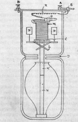
Referring to Fig. 1, the mains carrying the current are connected to the binding posts A and B. The current flowing through A passes through the switch S and resistance coils R, thence through the magnet L. The current is grounded on the upper frame of the lamp, as shown at C. The wire li is insulated from the upper frame work of the lamp, and the wire is grounded on the lower frame work. Thus 'it will be seen that the frame of the lamp is divided into two parts and insulated from each other at D. It follows, therefore, that when the carbons are inserted at M' and N, a passage for the current is provided and if we procure a mechanism to move the carbon M' upwards or the carbon N downwards, an arc will form between the carbons and light will result.
If the carbons are moved only a slight distance apart, a poor arc will be obtained, accompanied with little light; hence, to obtain a more powerful light the length of the arc must be increased, the amount of which will be dependent upon two factors, namely, the amount of the resistance cut in the circuit at R and the lifting power of the magnet M. If the magnet M is in good order and the arc still remains short, too much resistance is cut into the circuit, which must be lessened by moving the clip at O, thereby reducing the length of the resistance wire. The length of the are should now increase, and consequently a more powerful light should be obtained. If the clip D is moved so as to increase the resistance R, the arc will decrease.
Sometimes, no matter how much resistance is cut out, the arc will not increase in length. In this case it will be found that the magnet M is either wholly or partially burnt out, in which case the magnet must be replaced with a good one. Before discarding the injured magnet, however, it will be a good plan to test it, by allowing the current to How around it and then by placing a screwdriver or some iron or steel tool against the magnet. its lifting power can be determined. Should the magnet be found strong and therefore not burnt out, then the trouble will be either in the lilting mechanism shown at L or in the dash-pots shown at P and P.
The object of the dash-pots is to resist the lifting of the carbon too suddenly. Should the carbon be lilted with a " jerk," there is a possibility of drawing the carbon out of the field of the arc, thus breaking the arc and no light results. The correct working of the dash pot is an important factor of arc lighting, and to determine if it does operate correctly,.it should be seen that it requires considerable force to press the plunger into the pot quickly. From this it is learned that a blow or push will be resisted by the partial com-pression of the atmosphere, hence the sudden action of the magnet is controlled and the carbon is main tained within the field of the arc and light is formed the moment the contact of the carbons is broken.
Whenever a lamp becomes grounded, the movable carbon sometimes traverses its entire stroke without forming light. Of course, this ground must be removed and the simplest way to do it is to remove the outer shell or casing, then trip the lamp and throw on the current, when the ground should make its appearance and can be easily removed.
When continuous arcing occurs it will be found that the plungers of the dash pots are worn sufficiently to permit of a rapid lifting and dropping of the carbon and in such a case as this, satisfactory lighting is im-pos-ible. Sometimes the lamp will not burn satisfactorily, although the lamp mechanism and trimming are all right. This is often due to the arc traversing the perimeters of the carbons instead of being central.. Impurities in the carbons will cause this, and in order to overcome this difficulty, hollow and cored carbons, are employed.
In the latter case, the center of the carbons is filled with a soft carbon which is easily vaporized, thus lessening the tendency of the arc to traverse the circumference of the carbons, thereby preventing avoidable shadows. With enclosed arcs, when opalescent globes are employed, the shadows will not be noticeable to any great extent, as this form of globe diffuses the light more equally than clear globes.
It is important to have the upper carbon the hottest,: as this will deflect the light downwards. When an are lamp is first connected to the mains, it may not be wired so that the upper carbon will be the positive carbon. If, however, the current be thrown on and lamp allowed to burn for a few minutes and then out off the current, it can easily be seen which carbon is the hottest, and should the lower carbon be the hottest, the lead wires to the lamp must be reversed.
It is sometimes necessary to know what voltage is maintained across the arc. For this purpose, a portable voltmeter can be used and connected to the upper and lower carbons. The arc being formed, the voltmeter will register the necessary voltage to maintain the arc and by connecting the voltmeter to each arc in the circuit and by shifting the resistance in each lamp, an approximate equality of the voltage can be maintained throughout the various lamps and each lamp will properly do its share of the lighting.
The length of time a carbon will last depends upon the amount of air which is admitted to it; hence, to prolong the life of the carbon, the inner globe is often made as air-tight as possible. The inner and outer globes should be kept clean, as this will materially assist in the proper diffusion of the light.-"Practical Engineer." / .
Continue to:
My Books

