


"Sea Scout" Racing Yacht Model
Description
This section is from the book "Things To Make In Your Home Workshop", by Arthur Wakeling. Also available from Amazon: Things to Make in Your Home Workshop.
"Sea Scout" Racing Yacht Model
Model sailing is a sport for men as well as boys. Boy Scouts, Sea Scouts, and "good scouts" everywhere are building and racing model yachts.
For many, this desire to own and sail a boat finds expression in purchasing a toy boat. At best this is a makeshift compared with building one's own model from carefully designed plans of a yacht that really sails well, and in form and detail is as scientifically correct as any large racing craft.
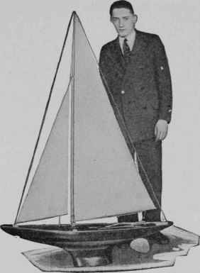
Fig. 45. - The 42-in. racing yacht model adopted as a standard design by the National Sea Scouts.

Fig. 46. - Yacht models built from the plans of A. M. Youngquist. of the Morrison R. Waite High School, Toledo, Ohio, before the start of a race. At the left is the Sea Scout model under sail.
High school boys in the Industrial Arts Department of the Morrison R.
Waite High School, Toledo, Ohio, who have been building model yachts for years, have experimented with many designs, ranging in size from 20 to 72 in. The most successful design for boys, and the one now adopted for model club and interschool competition in Toledo, is the 42-in. model Sea Scout (Figs. 45, 46, and 47).

Fig. 47. - Racing yacht models built under Mr. Youngquist's direction, and hulls in various stages of construction. The large yacht in the background is a 72-in. model.

Fig.48.- Working drawings of the Sea Scout hull showing how the lifts are cut out. how they are doweled and glued together, and how the final shaping is completed with the aid of carefully made templates.
This model has been recommended for adoption as the standard in the model building test by the Sea Scouts. A national program of racing contests in this class is under way in the Sea Scout organization. This is a challenge to boys everywhere to match their skill in building and racing these models. And it must be emphasized here that half the fun is in building them.

Fig. 49. - Plan showing the shape to which the lifts are cut. For a larger drawing of this and all other necessary plans, blueprints can be obtained. (Refer to the Appendix.).
The average cost of constructing the Sea Scout is between four and five dollars. The materials are easily obtained and no extensive equipment is needed.
Besides a workbench and woodworking vise, the following woodworking tools are required: jack plane or smoothing plane, spokeshave, chisel, gouge, try-square, hand screws, hammer, nail set, screw driver, brace and bits, crosscut and rip saws, keyhole saw, knife, and half-round cabinet, rasp. For making the fittings: flat file, rat-tail file, hand drill and set of drills, tinner's snips, hack saw, two or three small screw clamps, and a soldering outfit. A small metal vise is also desirable.
The hull is constructed on the "bread and butter" or lift method, which means that the seven layers of ¾-in. wood, marked A to G, Figs. 48, 49, and 50, must be cut accurately to the designed water lines and then glued together. The best wood is well-seasoned, clear white pine or sugar pine without checks. The grade of white pine used by pattern makers is the best, if obtainable. The Philippine wood often used in place of mahogany makes a beautiful model in a natural finish, although it is slightly heavier than white pine. Some of the Waite High School models are built of mahogany above the load water line and white pine below.
It is advisable to make manila paper half patterns for the lifts.6 These can be prepared by fairing the lines from the accompanying table of offsets. First establish center lines and accurately locate sections or station lines at right angles to the center line and 2 25/32 in. apart. On the station lines measure from the center lines the half-breadths given in the table. Bend thin wood strips or splines to pass through these points and draw the water lines.
When the half patterns have been cut out, mark accurate center lines on the wood. Secure a half pattern by means of thumb tacks to one of the pieces and draw a pencil line around the pattern. It is necessary also to transfer the section or station lines to the wood in order later to locate each layer in respect to every other layer.
Half Breadths Out From Center Line
STA. | DECK | A-W.L | B-W.L | C-WL. | D-L.W.L | E-W.L | F-W.L. | G-W.L | D-W.L. |
F.P. | 0 | ||||||||
1 | 5/16 | 1/32 | |||||||
2 | 7/32 | 1 1/16 | 23/32 | ||||||
3 | 2/16 | 1 31/32 | 1 25/32 | 1 5/16 | 0 | ||||
4 | 2 13/16 | 2¾ | 2 5/8 | 2 11/32 | 1 11/16 | 3/16 | |||
5 | 3 13/32 | 3 13/32 | 3 5/16, | 3 1/8 | 2 11/16 | 25/32 | ¼ | ||
6 | 3 27/32 | 3 27/32 | 3 13/16 | 3 23/32 | 3 3/8 | 2 25/32 | 1 13/32 | ¼ | |
7 | 4 3/32 | 4 3/32 | 4 1/16 | 3 7/8 | 3 13/32 | 2¼ | 25/32 | 5/16 | |
a | 4 5/32 | 4 7/32 | 4 7/32 | 4 1/16 | 3 11/16 | 2 5/8 | 15/16 | 13/32 | |
9 | 4 1/8 | 4 7/32 | 4¼ | 4 1/8 | 3 23/32 | 2 11/16 | 25/32 | 5/16 | |
10 | 4 1/32 | 4 3/32 | 4 3/32 | 3 15/16 | 3 7/16 | l 7/8 | 5/32 | ||
II | 3 27/32 | 3 7/8 | 3 13/16 | 3 9/16 | 2¾ | 3/16 | |||
12 | 3 15/32 | 3 15/32 | 3 11/32 | 2 13/16 | 5/16 | ||||
13 | 2 31/32 | 2 15/16 | 2 19/32 | 0 | |||||
14 | 2 7/16 | 2 7/16 | 2 7/32 | ||||||
15 | 1 13/16 | 1 13/16 | *DEADWOOD | ||||||
TRANSOM | 1½ | 1½ | |||||||
STATIONS SPACED - 2 25/32" | LENGTH OVER ALL-42" | ||||||||
WATER LINES SPACED- ¾" | LENGTH L.W.L. - 27 13/16" | ||||||||
DRAFT - 7" | BEAM LW.L- 8 1/8" | ||||||||
LEAD - 5.3 LBS. | SAIL AREA - 735 SQ. IN. | ||||||||
DISPLACEMENT - 390 CU.IN | RATING -22 | ||||||||
Turn the half pattern over and draw it for the other half of the water line. Do the same for each lift. Then cut the wood with saw, spokeshave, and plane accurately to the line, leaving square edges. To simplify the work of hollowing the hull, lifts A to E arc sawed out as shown by a perspective sketch of lift D in Fig. 48 and indicated in the views marked "lengthwise section" and "cross section." Use a keyhole or turning saw to cut out the interior of the lifts. Enough stock must be left for at least ½ in. of gluing surface between each subsequent layer, and at the ends an inch or more is left.
Continue to:


My Books

