Testing Small Engines
Description
This section is from the book "Wrinkles And Recipes, Compiled From The Scientific American", by Park Benjamin. Also available from Amazon: Wrinkles and Recipes, Compiled From The Scientific American.
Testing Small Engines
The apparatus needed is quite simple, and can be readily constructed by the young mechanic. The following embrace the principal points that are generally of interest in regard to engines and boilers: Diameter of cylinder, length of stroke, diameters of piston-rod, connecting-rod, crank-pin, valve-stem, fly-wheel, and shaft; lengths of connecting-rod and crank-pin, weights of whole engine and of fly-wheel, size of ports, stroke of valve, point at which steam is cut off, number of revolutions per minute, clearance at each end of cylinder, pressure of steam in boiler, dimensions and weight of boiler, diameters of steam-pipe and safety-valve, number of pounds of water evaporated, fuel burned per hour, and power of the engine. Many of these data are obtained at once, by direct measurement or weight. The diameter of the cylinder should be measured when it is at the temperature at which it is ordinarily maintained while running. The point of cut-off can generally be ascertained by removing the cover of the valve-chest, and observing the point at which the steam-valve closes when the engine is moved by hand. This should be done when the parts are heated. The clearance at each end of the cylinder includes not only the space between the piston and cylinder-head at the end of the stroke, but also the volume of the ports. A simple and accurate manner of measuring the clearance is to fill the cylinder with water, when the piston is at one end of the stroke, and then measure the water carefully in a cylindrical or rectangular vessel. The difference between the volume of the water and the volume of piston displacement (area of piston multiplied by length of stroke) will be the clearance. In measuring the piston displacement at the front end of the cylinder, the volume of the piston-rod (area of section of rod multiplied by length of stroke) must, of course, be deducted.
The number of revolutions of the engine per minute can be determined approximately by observation; but errors are apt to result, especially in the case of small engines moving at a high rate of speed. Small shaft-counters can be obtained at a very reasonable price, and measurements made with them are far more likely to be accurate.
Many small boilers are not provided with steam-gauges, so that the pressure of the steam can not be observed directly; but all such boilers have, or should have, safety-valves, and the pressure of the steam can be determined from them. Secure the valvestem of the safety-valve to the lever with wire or string, and attach a loop to the lever, into which pass the hook of an accurate spring-balance, arranging the loop so that it is directly over the centre of the valve-stem. Then take hold of the upper part of the spring-balance, and lift the valve slightly, noting the reading of the balance. Measure the lower diameter of the safety-valve, and find its area; divide the reading of the spring-balance by the area of the valve, and the result will be the pressure, in pounds per square inch, at which the steam will raise the safety-valve. Suppose, for instance, that the diameter of the safety-valve is 1 inch; its area will be about 7854/10000 of an inch. Now, if the tension of the spring-balance in raising the valve is 120 lbs., the pressure at which the valve will rise is the quotient arising from dividing 120 by 7854/10000, or 153 lbs. per square inch. It will be easy to make a table for any particular case, giving the pressure corresponding to each pound or fraction of a pound of tension in the balance; and by calculating in advance the reading of the balance for any given pressure, the weight can be adjusted on the lever until that tension is obtained, and the valve can thus be graduated to lift at any required pressure. Having determined the pressure at which the safety-valve will rise when the boiler is cold, raise the valve by means of the balance, from time to time, when the engine is working, and observe the tension. Find the pressure corresponding to this tension, and subtract it from the pressure at which the valve will be raised by the steam. The difference is the pressure in the boiler at the time. For example, suppose that in the last case the tension of the balance, on raising the valve when the engine was working, was 50 lbs. The pressure corresponding to this will be 50 divided by 7854/10000, or about 64 lbs., so that the pressure in the boiler at the time would be the difference between 153 and 64, or 89 lbs. per square inch. By preparing a table showing the pressure in the boiler due to each pound of tension in the spring balance, the pressure at any time can be read off as soon as the indication of the balance is observed.
The amount of water evaporated per hour and the fuel burned can, of course, be readily determined by measurement, drawing the water from a tank of known dimensions, and observing its state at the commencement and close of a trial, being careful to leave the water in the boiler at the same height at which it was at the commencement, and maintaining this height as constant as possible during the experiment. In measuring the fuel consumed, it is best to draw out the fire at the commencement of the trial, rekindling it as soon as possible, and charging all the fuel used from that time, hauling and quenching the fire immediately at the close of the trial, and weighing back all fuel that is uncon sumed. In the case of small boilers heated by lamps, a measurement of the oil used between the beginning and end of the trial will generally be sufficient; and if gas is employed as fuel, it will be necessary to attach a meter to the pipe, to determine the quantity consumed in any given time
To ascertain the power of the engine, the most convenient method is, generally, to attach a friction-brake, shown in the accompanying engraving, to the band-wheel. Hollow out two pieces of wood, Band C, so that they will lit the circumference of the band-wheel, A, and attach light plates of metal, D and E, to the sides, so that the pieces of wood can not slip off when secured in position. Provide two belts, F, G, countersinking the heads, H and I, into the upper piece of wood, so that they can not turn, and put nuts and washers, K and L, on the other ends, so that the two pieces of wood can be clamped on the band- wheel as tightly as is necessary. Make the upper piece of wood somewhat longer than the other, and pass a rod, M, through the end. On this rod weights, N, are to be placed, and the lower end of the rod is hooked to the piston-rod of a small cylinder, O. The piston, P, fits loosely in this cylinder, which is filled with oil or water; and the piston has small holes in it, so that it can move up and down without much resistance, if moved slowly, but offers considerable resistance to sudden motion. The action of the apparatus will doubtless be apparent to our readers. By tightening the nuts on the bolts, F, G, there will be considerable friction between the band-wheel and the pieces of wood. The rod M must then be loaded with sufficient weight, so that the engine can just move at its regular rate of speed, and keep the upper piece of wood in a horizontal position. The friction on the band-wheel will cause it to become heated, unless some arrangements are made for cooling, either by keeping a stream of water running upon it, or immersing the lower part in a trough in which the water is constantly changed. The small cylinder, O, and piston, P, serve to counteract the effect of sudden shocks, which would otherwise throw the arm of the piece B from a horizontal position. Now it will be plain that, as the band-wheel revolves (constantly maintaining the arm, with the weight attached, in a horizontal position), the effect is the same as if it were lifting this weight by means of a rope running over a windlass, and the distance through which it would lift the weight in a given time is the same as the weight would move if the whole apparatus were free to revolve. If, for example, the wheel makes 300 revolutions in a minute, the distance from the centre of the wheel to the centre of the weight is 1 foot, and the weight is 10 lbs.; this weight, if free to revolve, would move in each revolution through the circumference of a circle whose radius is 1 foot, and in a minute would move 300 times as far, or about 1885 feet. The work of the engine in a minute, then, will be that required to lift. 10 lbs. through a height of 1885 feet, or 18, 850 foot lbs.; and as one horse-power is the work represented by 33, 000 foot lbs. per minute, the engine would be developing a little more than half a horse-power.
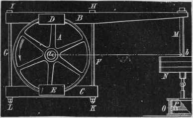
The Friction-Brake
In making experiments with the friction-brake, the apparatus should be placed loosely on the band-wheel; and before the weights are attached, a spring-balance should be secured to the arm, at the centre of the hole for the rod M, and the reading noted when the arm is in a horizontal position. This reading must be added to the weights that are afterwards attached. The horizontal distance from the centre of the wheel to the centre of the rod M, should be carefully measured. Then start the engine, with the throttle-valve wide open, and screw up the nuts K L gradually, adding weights at X. It will then only be necessary, when sufficient weights are added, to keep the wheel cool, and occasionally adjust the nuts K L, should the brake bind or become too loose from any cause. Should it be difficult or inconvenient to maintain the arm in a horizontal position, note carefully the position it assumes during the test; and for the radius to be used in the calculation, measure the distance a b from the centre of the wheel to the centre of the rod M, in a direction perpendicular to the direction of the rod.
Instead of the weights, X, and cylinder, O, a spring-balance may be attached to the end of the rod M, and secured to some fixed support, its readings during the trial being used in place of the attached weights. In this case, also, the weight of the apparatus must be first determined, and added to the readings of the spring-balance. The plan represented in the engraving is, however, the best.
The above are, in detail, the methods to be pursued in preparing a report of the performance of small engines and boilers. Although they are far from fulfilling all the requirements of a scientific test, they will give very accurate results if carefully conducted. B.
Continue to:
My Books

