Setting Slide-Valve
Description
This section is from the book "Wrinkles And Recipes, Compiled From The Scientific American", by Park Benjamin. Also available from Amazon: Wrinkles and Recipes, Compiled From The Scientific American.
Setting Slide-Valve
The methods of adjusting the lap and travel of slide valves, and the position of the eccentric, given below, are taken, with some slight modifications, from the work of Dr. Zeuner, on Slide-Valve Gearing, It is believed that the simplicity of the construction will be appreciated by the reader.
I. Area Of Ports
To find the proper area of port for an engine of a given piston-speed, multiply the area of the piston, in square inches, by the number nearest to the given piston-speed in the table on the next page.
Setting The Slide-Valve
Speed of piston, in feet, per minute. | Number by which area of piston is to be multiplied. |
100 | 0.02 |
200 | 0.04 |
300 | 0.06 |
400 | 0.07 |
500 | 0.09 |
600 | 0.1 |
700 | 0.12 |
800 | 0.14 |
900 | 0.15 |
1000 | 0.17 |
1100 | 0.19 |
1200 | 0.2 |
1300 | 0.22 |
1400 | 0.24 |
1500 | 0.25 |
II. Lap, Lead, And Travel Of Valve
The amount of opening given by the valve for the admission of steam or its exhaust, at the commencement or termination, respectively, of the stroke of an engine, is called the lead, either steam or exhaust, as the case may be. If the face of the valve is wider than the port, the excess of width is called lap, and may be either steam or exhaust lap. Steam lap is an excess of width on the outer extremities of the valve-faces, and exhaust-lap an excess on the inner faces. The effect of steam lap is to cut off the steam at an earlier point of the stroke, and exhaust-lap causes the exhaust to open later and close earlier than it otherwise would. It must be obvious that the action of the exhaust would be very much deranged if an attempt was made to cut off very short, and it is found, in practice, that the limiting point of cut-off with the simple slide-valve is at about two thirds of the stroke.
The travel of the valve is the distance between its two extreme positions. For a valve without lap or lead, the travel is equal to twice the width of the steam-port. If lap is added, the travel of the valve is equal to twice the width of the port, increased by twice the amount of steam- lap on one end.
III. The Eccentric
The eccentric, which moves the valve, is a substitute for the crank, and consists of a circular disk secured to the shaft, the centre of the disk lying outside of the centre of the shaft. The distance between the centres of the eccentric, and the shaft is equal to half the travel of the valve. If a valve has neither lap nor lead, the eccentric is secured to the shaft in such a position that a line joining its centre with the centre of a shaft is perpendicular to a line connecting the centre of the shaft and the centre of the crank-pin. If the valve has lead, the eccentric must be turned on the shaft sufficiently to secure the desired amount, and If lap is also added to the steam side, the eccentric must be advanced still further. In either of these cases, the amount the eccentric is moved forward is termed the angular advance of the eccentric, being the angle made by a line joining the centres of the eccentric and shaft with a line drawn through the centre of the shaft perpendicular to the line of centres of the crank-pin and shaft. The points in which these two perpendicular lines intersect the shaft should be plainly marked by a centre-punch or chisel, for convenience in adjusting the eccentric.
IV. Proportions Of Valve And Seat
The bridge of the valve-seat should generally have a width equal to the thickness of the cylinder. The width of the exhaust-port is found by adding the width of the steam-port to the half-travel of the valve, and subtracting the width of the bridge.
The length of the valve is equal to the width of the exhaust-port, increased by the width of the bridges and the two faces.
V. To Find The Lap And Travel Of The Valve, And Angular Advance Of The Eccentric, For Given Points Of Admission, Cut-Off, And Release
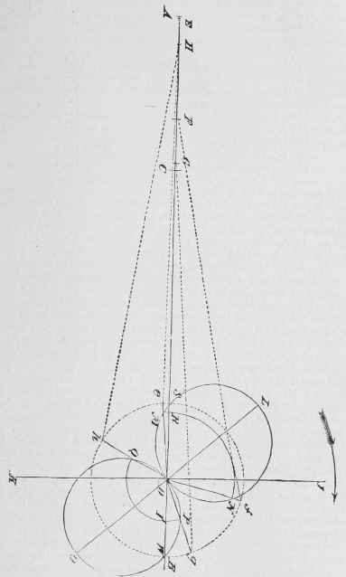
Draw a horizontal line, A B, and lay off on it, any distance, A C, to represent the length of stroke of the engine. Make E S equal to the length of the connecting-rod between centres, and S D equal to one half of A C. With D as a centre, and D S as a radius, describe a circle, which represents the path described by the centre of the crank-pin. The arrow shows the assumed direction of the motion of the engine. Assume some point, E, at which it is desired to have the steam-valve begin to open when the piston has still to complete the portion E A of its return stroke. Assume also a point, F, at which the steam is to be cut off when the piston has advanced a distance, E F, and a point, G, at which the exhaust-valve is to be begin to open when the piston has completed the portion E G of the stroke. Then, with each of these points, E, F, G, as a centre, and with the length of connecting-rod, A 8, as a radius, describe an arc of a circle cutting the path of the crank-pin in the three points e, f, g. Join each of these points with the point D, thus determining the position, D e, of the crank at the instant of admission, its position, D f, at the instant of cut-off, and its position, D g, at the instant of release. Bisect the angle e Df by a straight line, D L; make D L of any convenient length, and upon it, as a diameter, describe a circle, and note the point, M, in which it cuts D e. From D as a centre, and with D M as a radius, describe an arc of a circle, M R N. Measure the lengths of the lines D M and D L, and divide the former by the latter. Subtract the quotient from 1, and divide the width of steam-port by the difference. This gives the travel of the valve. Multiply the travel of the valve by half the quotient obtained above, and the product will be the steam-lap. The angle L D I is the angular advance of the eccentric, Divide the length of S R by the length of L D, and multiply half the quotient by the travel of the valve: the product is the steam-lead.
Next produce the line L D, making D 0 equal to D L, and upon D 0, as a diameter, describe a circle, noting the point, P, in which it cuts D g, the position of the crank at the instant of release. Divide the length of D P by the length of D 0, and multiply half the quotient by the travel of the valve, which gives the exhaust-lap. With D as a centre, and D P as a radius, describe an arc, P T Q, noting the points, T and Q, in which it cuts A B, and the circle whose diameter is D 0. Divide the length of T W by the length of D 0, and multiply half the quotient by the travel of the valve: the product is the exhaust-lead. Through the point Q draw the line D h: this is the position of the crank at the instant the exhaust-valve closes and cushion commences. With h as a centre, and A S, the length of the connecting-rod, as a radius, describe an arc cutting the line A B in the point H; then C H is the portion of the return stroke completed when the exhaust-valve closes.
On account of the angularity of the connecting-rod, the points of cut-off and exhaust closure will vary somewhat on the return stroke. They can be equalized by a slight change in the angular advance and length of the eccentric rod.
VI. Example
The following example will serve to illustrate the application of the preceding principles:
A valve is to be designed for an engine having a cylinder 20 inches in diameter, and a stroke of 2-1/2 feet, making 80 revolutions a minute. The length of the connecting-rod is 6-1/4 feet. The valve-is to admit steam when the piston has made 0.997 of the stroke, is to close the steam-port at two thirds of the stroke, and open the exhaust when 95/100 of the stroke has been completed.
The area of the piston, in square inches, is 0.7854 times 400 (the square of 20), or 314.16, and the piston-speed is 400 feet per minute; hence the proper port area is 0.07 times 314.16, or about 22 square inches. Assuming the length of the port to be equal to the diameter of the cylinder, 20 inches, its width will be .1/20 of 22, or 1.1 inches. The width of the bridge must be equal to the thickness of the cylinder, or 1-1/8 inches. In the figure, make E S equal to 2-1/2 times A C, and E A, 0.997 of A C, A F, 2/8 of A C, and A G, 0.95 of A G. Constructing the positions of the crank corresponding to these points of stroke, and making the other constructions as explained above, suppose that the data obtained from the figure by measurement are as follows:
Angle RD M, 5°; angle M D N, 108-3/4; angle R D P, 151-1/20 angleT D Q, 137-1/40; angle L D I, angular advance of eccentric, 40-5/8°; DM, 0.65ofan inch; DLand DO, each 1.5inches; D P, 0.19of an inch; S R, 0.1 of an inch; T W. 0.375 of an inch;
C II, part of return stroke completed when exhaust closes, 0.85. Dividing D M (0.6.-)) by D L (1.5), the quotient is 0.43+; subtracting 0.43 from 1. the remainder is 0.57; dividing twice the width of steam-port, 2.2, by 0.57, the quotient, the travel of the valve, is 3.86 inches. Multiplying 1/2 of 0.43 by 3.86, the product, the steam-lap, is 0.83 of an inch. Dividing DP(0.19)by D0(1.5), the quotient is 0.127: multiplying 1/2 of 0.127 by 3.86, the product, the exhaust-lap, is 0.25of an inch. Dividing SR (0.1)by 1.5. the quotient is 0.067; multiplying 1/2 of 0.067 by 3.86, the product, the steam lead, is0.13 of an inch. Dividing T W(0.375) by 1.5. the quotient is 0.25: multiplying of 0.25 by 3.86, the product, the exhaust-lead, is 0.48 of an inch. Adding the half-travel of the valve (1.93) to the width of the steam port, 1.1. the sum is 3.03; ubtracting the width of the bridge (1.125), the- remainder, the width of the exhaust-port, is 1.91 in. The sum of the steam lap (0 88), the exhaust-lap (0.25), and the width of the steam port (1.1), the length of tin valve- face, is 2.18 inches. The sum of twice the length of face (4.36), twice the width of bridge (2.25), and the width of the exhaust port (1.91), the length of valve. is 8.52 inches. In this example no attempt has been made to secure great accuracy, and, as the measurements were made from a small sketch, there may be considerable errors. In practice, a scale reading to hundredths of an inch should be used, and the figure should be constructed of full size, if possible. This can generally be done by laying down the positions of the crank in a small sketch, and then transferring them to a large drawing; or the positions may either be calculated or taken from a crank-table, if one is available. By making the drawing full size, and having marks on the shaft as described above, a template can be constructed from the drawing, for transferring the position of the eccentric to the shaft. It may be remarked, that however carefully the valve is proportioned and the adjustment of the eccentric effected, the engineer who desires to be certain that the valve-motion of his engine is properly arranged, will make the final test and adjustments with the aid of the steam-engine indicator. B.
Continue to:
My Books

