The Indicator
Description
This section is from the book "Wrinkles And Recipes, Compiled From The Scientific American", by Park Benjamin. Also available from Amazon: Wrinkles and Recipes, Compiled From The Scientific American.
The Indicator
The indicator is a recording steam-gauge, very accurately made, for determining the pressure acting on the piston of an engine, at every point of the stroke. It is connected to the cylinder, close to one end, and when the cock, seen in Fig. 1, is opened, the steam presses on a small piston, shown in Fig. 2. A stiff spiral spring above this piston is compressed by the pressure of the steam. The piston-rod, it will be seen, is connected to a lever, and this, in turn, with a link and another lever, a pencil or marking-point being placed in a hole in the link. There is a cylindrical barrel to the left on which a piece of paper can be placed, being held by two clip springs. This barrel can be made to revolve by pulling a string wound round the bottom, and it has within it a coiled spring, which makes it turn back again when the tension of the string is relaxed. Now, suppose that the indicator is attached to the cylinder of an engine, and the cord is fastened to some moving part, so that when the engine makes a stroke it causes the barrel carrying the paper to revolve, and on the return stroke the coiled spring in this paper barrel makes it turn back to its original position. Meanwhile the steam in the cylinder is pressing on the piston of the indicator, forcing it up a distance corresponding to the pressure, so that if the pencil is allowed to touch the paper, it will trace out a line which represents the pressure, and this line is called an indicator diagram. Such a diagram is shown in Fig. 7. The atmospheric line, C D, is traced when the cock is closed and there is no pressure on the piston. At b, the stroke of the engine commences, and when the piston has gone about half way to the other end of the cylinder, the steam is cut off, as shown at c, and the pressure begins to fall as the steam expands. Near the end of the stroke, the exhaust-valve opens, as shown at d, and the pressure falls more rapidly. When the engine makes the return stroke, there is only the back pressure, until near the end, when the exhaust-valve closes, shown at f, and the steam being compressed, the pressure rises. Just before the end of the stroke, at a, on the diagram, steam is admitted, and the pressure rises suddenly.
I. How To Attach The Indicator To The Cylinder Of An Engine
Drill a hole in the cylinder, in the head, or close to the end, and tap it out for a half-inch iron nipple. The indicator-cock must be connected to this, using an elbow, if necessary, and then the indicator can be attached at pleasure. In drilling this hole, do not make it close to the ports. Sometimes the connections from the two ends of a cylinder are brought together, and one indicator is made to answer for both ends, a cock being fitted in each pipe, so that either can be opened to the indicator, as desired. In such a case, the holes in the cylinder should be larger, for three-quarter inch pipe, at least, so as to prevent any loss of pressure. It is obvious, however, that as the indicator is used to obtain the pressure in a cylinder, the more closely and directly it is connected, the better.
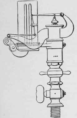
Fig. 1.
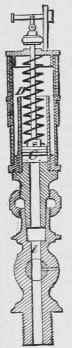
Fig. 2. The Indicator
II. How To Make The Paper Barrel Have A Motion Coincident With That Of The Piston
A. Reducing-wheel.-Fig. 3.
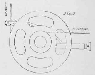
This is attached to some part of the engine-frame, and the cord marked "to engine" is made fast to the cross- head, being carried over a pulley, if necessary, so that it is parallel to the guides. The other cord i- fastened to the cord wound round the paper barrel of the indicator. The two wheels hear the same proportion to each other as the stroke of the engine does to the desired range of motion for the paper barrel, the latter being usually from 1 to 5 inches. There is a coiled spring in the reducing-wheel, which makes it turn back on the return movement of the cross-head. By having different sized wheels to carry the cord leading to the indicator, this arrangement can be adapted to engines with different strokes.
b. Swinging-board, with slot.-Fig. 4.
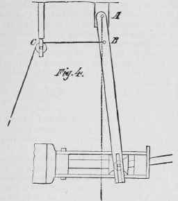
Mark a point, A, at some convenient distance from the cross-head, and on a line perpendicular to the guides, at the centre of the stroke. Attach a board so that it can swing freely around this point; cut a slot in the other end, for a pin connected to the cross-head. Then, as the cross-head moves, it will make the board swing to and fro. At some point B, of the board, which has the proper movement for the paper cylinder, attach a corn or wire, and carry it over a pulley, C, adjusted at such a height that the part of the cord, B C, is parallel to the guides when the engine is at half stroke. The cord can then be brought down and attached to the cord of the paper barrel.
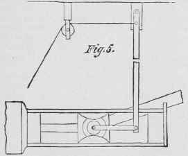
C. Swinging-board, with link.-Fig. 5.
Sometimes it is not practicable to attach the board directly to the cross-head by a pin, and it is more convenient to use a link connection, the arrangement of which will be evident from the figure.
It is easy to see that a number of arrangements could be devised on the general principle of the swinging-board. Sometimes it is attached to the guides by a standard, and sometimes one end is connected to the cross-head and the other to the indicator, the point around which the board swings being between, at distances from the two ends proportional to the stroke of the engine and the movement of the paper barrel. Whatever the special arrangement, attention should be given to these two points:
1st. To have the board perpendicular to the guides when the engine is at half stroke.
2d. To lead the cord off in a direction parallel to the guides.
III. How To Take An Indicator Diagram
If a cord is used for the motion, it should have a slide on it, so that it can be adjusted, and it should have a hook so that it can be attached to the cord of the paper barrel, and detached at pleasure. Fine wire is better than cord, as it is quite flexible, and does not stretch so readily. If several cards, taken at intervals, are of the same length, the connection is all right. Having got the motion properly adjusted, turn the cock of the indicator so that it will blow through, having first put a piece of paper on the paper barrel. Then turn the cock so as to let steam into the indicator, and press the pencil lightly against the paper; draw it back as soon as the card is traced, shut the indicator-cock, and apply the pencil again, to trace the atmospheric line-be particular not to trace the atmospheric line until the diagram is taken; then unhook the cord, remove the diagram from the paper cylinder, and mark on it the pressure of steam by gauge, the revolutions per minute, the height of the barometer, and the temperature of the engine-room-if the proper instruments are available-and the vacuum by gauge, the temperature of the hot-well, and the temperature of the injection-water, if the diagram has been taken from a condensing-engine. All the dimensions of the engine should also be noted, for future reference, together with such particulars in regard to the dimensions and performance of the boiler as can be obtained.
A counter should always be employed to determine the number of revolutions per minute, at the time the diagram is taken. It can be connected to the indicator motion, or to some moving part of the engine. Take its reading at the beginning of a minute, and at the end, having indicated the engine meanwhile. This gives the revolutions at the time the card was taken, with considerable accuracy.
Continue to:
My Books

