The Indicator. Continued
Description
This section is from the book "Wrinkles And Recipes, Compiled From The Scientific American", by Park Benjamin. Also available from Amazon: Wrinkles and Recipes, Compiled From The Scientific American.
The Indicator. Continued
IV. How To Draw The True Diagram
The indicator diagram from .......end of the cylinder, it is evident, only shows what takes place on the side of the piston on which the indicator is applied hut at the same time there is some back pressure on the other Bide, opposing the motion of the piston. To get the actual diagram, therefore, it is necessary to take diagrams from both ends of the cylinder simultaneously, and then combine the parts of each that were traced at the same time. Thus such a figure as is shown in Fig. 6 is obtained. On one side of the piston, the line a b c f is traced, and d c e is traced at the same time on the other, and the figure so obtained is the true diagram representing the distribution of the pressure. In using the diagram as ordinarily taken, therefore, the actual effective pressure is not obtained; but there is no error in practice, since the inaccuracies of the diagrams from the two sides balance each other. It is a great mistake, however, to take diagrams from one end of a cylinder only, and assume that those from the other would be similar. Quite often there are serious differences, and both ends of a cylinder should always be indicated, if possible a. 1st method.-Draw perpendiculars to the atmospheric line, from the extremities of the diagram, thus determining its length, C D; divide the line, V D, into 10 equal parts, and midway between each of the divisions erect a perpendicular to C D, drawing it between the upper and lower boundaries of the diagram; measure the length of each of these lines on the scale of the indicator-spring, add the measurements together, and divide the sum by 10. In the figure, the pressure, or length of the line on the scale, is shown at each perpendicular. The sum of these is 363, so that the mean effective pressure is 36.3 lbs. per square inch.
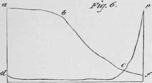
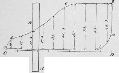
Fig.7.
b. 2d method. - Draw perpendiculars between the ten divisions of C D, as explained above. Then take a strip of paper, apply it to the first perpendicular, and mark the length; apply it to the next perpendicular, and mark its length, next to the first; so continue applying it to each, and when the last perpendicular has been measured, the distance between the first and last marks will be the sum of all the lengths. The strip of paper, A B, is shown in the figure as applied to the third perpendicular. Measure the length of the paper between the extreme marks, in inches, multiply it by the scale of the indicator-spring, and divide by 10. Suppose, in the present case, that the length of the paper is found to be 12.1 inches, and that each inch represents 30 lbs. on the scale of the indicator-spring; 30 times 12.1 is 363, so that the mean effective pressure is 36.3 lbs. per square inch, as before.
C. Positive and negative pressure. - Fig. 8.
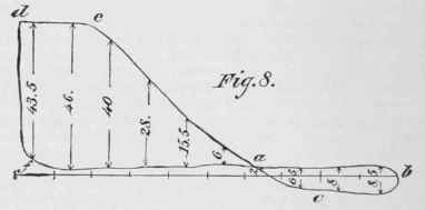
When the steam is cut off very early in the stroke, and the valves and piston are tight, a diagram is sometimes drawn like that in the figure, in which the hark pressure is greater than the forward pressure for a portion of the stroke, and the pressure determined from the portion of the diagram a c b must be subtracted from the pressure due to the portion d e a f. In such a case, the method of determining the mean pressure is as follows: Divide the atmospheric line into 10 equal parts, as before, and draw perpendiculars midway between them; add together the perpendiculars (measured in the scale of the indicator-spring) in the positive part of the diagram, also those in the negative part; subtract the latter from the first sum, and divide the difference by 10. In the figure, the pressures at the different perpendiculars are given. The sum of the positive pressures is 179, of the negative pressures 35, and the difference is 154; so that the mean effective pressure is 15.4 lbs. per square inch.
VI. How To Find The Indicated Horse Power Of A Steam-Engine
Having determined the mean effective pressure from a diagram, by one of the methods explained above, multiply this pressure by the product of the stroke in feet, the square of the diameter of the cylinder in inches, the number of revolutions per minute, and 0.0000476.
Example.-Suppose the mean effective pressure is 50 lbs. per square inch, the diameter of the cylinder 15 inches, the length of stroke 2 feet, and the number of revolutions per minute 80. Then the horse-power is the product of 50, 225 (the square of 15), 80. and 0.0000476, or 85.68.
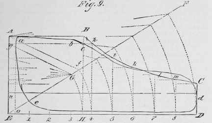
This is the diagram that would be taken if the steam acted in the cylinder with the pressure at the beginning of the stroke until the point of cut-off, and that then the admission ceased instantaneously, and the steam expanded, in accordance with Mariotte's law, to the end of the stroke, when the exhaust-valve opened, and the steam was immediately condensed, creating a perfect vacuum in the cylinder for the return stroke. Such a diagram is represented by A B C D E, this being the theoretical diagram for the actual diagram, a b c d e. The following is the method of laying it down: Draw a line, E D, at a distance below the atmospheric line, n d, equal to the pressure of the atmosphere (14.7 lbs. per square inch on an average), on the scale of the diagram; mark on E D the length, o D, of the actual diagram; then find the total volume of the clearance spaces at the end of the cylinder from which the diagram was taken, and make o E bear the same relation to o D as this volume of clearance has to the total volume swept through by the piston per stroke. To make this plain, suppose that in a cylinder having a diameter of 24 inches and a stroke of 3 feet, it is found that the volume of the clearance spaces at one end of the cylinder is 900 cubic inches. The volume swept through by the piston per stroke is the product of 0.7854, 24 squared, and 36 or 17, 286 cubic inches, so that the clearance is about 52/1000 of the piston displacement, and o E must be made 52/1000 as long as o D. Thus, if o D is 5 inches, o E must be 26/100 of an inch. Having determined the point E, make E A perpendicular to E D, and draw a line, A B, parallel to E D, at such a height that it represents the initial pressure of the steam. Through c, on the actual diagram, where the steam is cut off, draw a perpendicular, B H, to E D. Divide E D into any number of equal parts, and erect perpendiculars at the points of division that are beyond the point of cut-off. From E draw any diagonal line, E F, and from E as a centre, with a radius EII, draw an arc cutting E F in the point G. From the same centre, and with radii equal to E 4, E 5, etc., draw arcs cutting E F. The arc drawn with a radius E 4, cuts E F in the point .f Draw the line f A, and from G draw a line, G g, parallel to f A. From g draw a line, g h, parallel to f A, and the point h, in which it cuts the perpendicular drawn through 4, is a point of the curve of expansion. The construction of the points on the other perpendiculars is precisely similar, and is indicated in the figure. Having determined a sufficient number of points, draw through them the curve of expansion, B h i k I m c, and the theoretical diagram will be completed.
This kind of diagram is useful for comparing the merits of different engines, since it is evident that, other things being equal, the engine whose actual diagram most closely approaches the theoretical is the best. The mean pressure, as shown by such a diagram, can be determined by one of the methods already explained, for comparison with the pressure given by the actual diagram.
VIII. How To Take Care Of The Indicator
Always oil the cylinder and all moving parts before applying the instrument to an engine. Never use anything but the finest grade of oil, such as that specially prepared for sewing-machines or clocks. After taking one or two diagrams, remove the indicator, and examine its steam-Cylinder. If any grit has entered, wipe it out, using soft cotton-waste on the end of a white-pine stick. It is important to attend to this on indicating an engine of which the condition is not known, and if it is found that dirt or grit is forced into the indicator, it should be cleaned a1 frequent intervals during the experiments.
As soon as the experiments have been concluded, remove the indicator, and when it has cooled sufficiently, wipe it out and apply oil in the steam cylinder, and to all the moving parts. Be careful to dry the spring thoroughly, and cover it with oil. Never put any hard substance into the steam cylinder, but use a white-pine stick and soft cotton-waste. After use, take out the plug of the indicator-cock, clean it and the seat, apply oil. and on replacing it adjust it so that it moves freely and does not leak.
It might he supposed that minute directions of this kind were Superfluous, and that anyone owning an indicator would see the necessity of using such a delicate instrument with great care.
The generality of the indicators in common use, however, impress the observer with the idea that all the directions recited above have been studiously neglected B.
Continue to:
My Books

