


Planetary Wheel-Trains. II
Description
This section is from "Scientific American Supplement". Also available from Amazon: Scientific American Reference Book.
Planetary Wheel-Trains. II
By Prof. C.W. MACCORD, Sc.D.
PLANETARY WHEEL TRAINS. Fig. 14
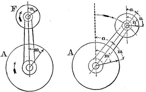
It has already been shown that the rotations of all the wheels of a planetary train, relatively to the train-arm, are the same when the arm is in motion as they would be if it were fixed. Now, in Fig. 14, let A be the first and F the last wheel of an incomplete train, that is, one having but one sun-wheel. As before, let these be so connected by intermediate gearing that, when T is stationary, a rotation of A through m degrees shall drive F through n degrees: and also as before, let T in the same time move through a degrees. Then, if m' represent the total motion of A, we have again,
m' = m + a, or m = m' - a.
This is, clearly, the motion of A relatively to the fixed frame of the machine; and is measured from a fixed vertical line through the center of A. Now, if we wish to express the total motion of F relatively to the same fixed frame, we must measure it from a vertical line through the center of F, wherever that maybe; which gives in this case:
n' = n + a, or n = n' - a.
but with respect to the train-arm when at rest, we have:
| ang. vel. A ang. vel. F | = | n m | , whence again, |
| n' - a m' - a | = | n m | . |
This is the manner in which the equation is deduced by Prof. Willis, who expressly states that it applies whether the last wheel F is or is not concentric with the first wheel A, and also that the train may be composed of any combinations which transmit rotation with both a constant velocity ratio and a constant directional relation. He designates the quantities m', n', absolute revolutions, as distinguished from the relative revolutions (that is, revolutions relatively to the train-arm), indicated by the quantities m, n: adding, "Hence it appears that the absolute revolutions of the wheels of epicyclic trains are equal to the sum of their relative revolutions to the arm, and of the arm itself, when they take place in the same direction, and equal to the difference of these revolutions when in the opposite direction."
In this deduction of the formula, as in that of Prof. Rankine, all the motions are supposed to have the same direction, corresponding to that of the hands of the clock; and in its application to any given train, the signs of the terms must be changed in case of any contrary motion, as explained in the preceding article.
And both the deduction and the application, in reference to these incomplete trains in which the last wheel is carried by the train-arm, clearly involve and depend upon the resolving of a motion of revolution into the components of a circular translation and a rotation, in the manner previously discussed.

PLANETARY WHEEL TRAINS. Fig. 15
To illustrate: Take the simple case of two equal wheels, Fig. 15, of which the central one A is fixed. Supposing first A for the moment released and the arm to be fixed, we see that the two wheels will turn in opposite directions with equal velocities, which gives n/m = -1; but when A is fixed and T revolves, we have m' = 0, whence in the general formula
| n' - a -a | = -1, or n' = 2 a; |
which means, being interpreted, that F makes two rotations about its axis during one revolution of T, and in the same direction. Again, let A and F be equal in the 3-wheel train, Fig. 16, the former being fixed as before. In this case we have:
| n m | = 1, m' = 0, which gives |
| n' - a -a | = 1, ∴ n' = 0; |
that is to say, the wheel F, which now evidently has a motion of circular translation, does not rotate at all about its axis during the revolution of the train-arm.

PLANETARY WHEEL TRAINS. Fig. 16
All this is perfectly consistent, clearly, with the hypothesis that the motion of circular translation is a simple one, and the motion of revolution about a fixed axis is a compound one.
Whether the hypothesis was made to substantiate the formula, or the formula constructed to suit the hypothesis, is not a matter of consequence. In either case, no difficulty will arise so long as the equation is applied only to cases in which, as in those here mentioned, that motion of revolution can be resolved into those components.
When the definition of an epicyclic train is restricted as it is by Prof. Rankine, the consideration of the hypothesis in question is entirely eliminated, and whether it be accepted or rejected, the whole matter is reduced to merely adding the motion of the train-arm to the rotation of each sun-wheel.
But in attempting to apply this formula in analyzing the action of an incomplete train, we are required to add this motion of the train-arm, not only to that of a sun-wheel, but to that of a planet-wheel. This is evidently possible in the examples shown in Figs. 15 and 16, because the motions to be added are in all respects similar: the trains are composed of spur-wheels, and the motions, whether of revolution, translation, or rotation, take place in parallel planes perpendicular to parallel axes. This condition, which we have emphasized, be it observed, must hold true with regard to the motions of the first and last wheels and the train-arm, in order to make this addition possible. It is not essential that spur-wheels should be used exclusively or even at all; for instance, in Fig. 16, A and F may be made bevel or screw-wheels, without affecting the action or the analysis; but the train-arm in all cases revolves around the central axis of the system, that is, about the axis of A, and to this the axis of F must be parallel, in order to render the deduction of the formula, as made by Prof. Willis, and also by Prof. Goodeve, correct, or even possible.

PLANETARY WHEEL TRAINS. Fig. 17
This will be seen by an examination of Fig. 17; in which A and B are two equal spur-wheels, E and F two equal bevel wheels, B and E being secured to the same shaft, and A being fixed to the frame H. As the arm T goes round, B will also turn in its bearings in the same direction: let this direction be that of the clock, when the apparatus is viewed from above, then the motion of F will also have the same direction, when viewed from the central vertical axis, as shown at F': and let these directions be considered as positive. It is perfectly clear that F will turn in its bearings, in the direction indicated, at a rate precisely equal to that of the train-arm. Let P be a pointer carried by F, and R a dial fixed to T; and let the pointer be vertical when OO is the plane containing the axes of A, B, and E. Then, when F has gone through any angle a measured from OO, the pointer will have turned from its original vertical position through an equal angle, as shown also at F'.
Now, there is no conceivable sense in which the motion of T can be said to be added to the rotation of F about its axis, and the expression "absolute revolution," as applied to the motion of the last wheel in this train, is absolutely meaningless.
Nevertheless, Prof. Goodeve states (Elements of Mechanism, p. 165) that "We may of course apply the general formula in the case of bevel wheels just as in that of spur wheels." Let us try the experiment; when the train-arm is stationary, and A released and turned to the right, F turns to the left at the same rate, whence:
| n m | = -1; also m'= 0 when A is fixed, |
and the equation becomes
| n' - a - a | = -1, ∴ n' = 2 a: |
or in other words F turns twice on its axis during one revolution of T: a result too palpably absurd to require any comment. We have seen that this identical result was obtained in the case of Fig. 15, and it would, of course, be the same were the formula applied to Figs. 5 and 6; whereas it has never, so far as we are aware, been pretended that a miter or a bevel wheel will make more than one rotation about its axis in rolling once around an equal fixed one.
Again, if the formula be general, it should apply equally well to a train of screw wheels: let us take, for example, the single pair shown in Fig. 8, of which, when T is fixed, the velocity ratio is unity. The directional relation, however, depends upon the direction in which the wheels are twisted: so that in applying the formula, we shall have n/m = +1, if the helices of both wheels are right handed, and n/m = -1, if they are both left handed. Thus the formula leads to the surprising conclusion, that when A is fixed and T revolves, the planet-wheel B will revolve about its axis twice as fast as T moves, in one case, while in the other it will not revolve at all.
PLANETARY WHEEL TRAINS. Fig. 18
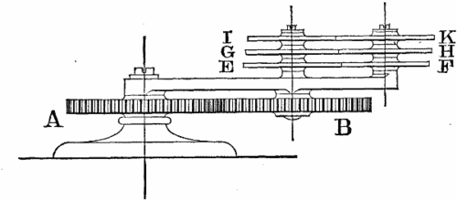
A favorite illustration of the peculiarities of epicyclic mechanism, introduced both by Prof. Willis and Prof. Goodeve, is found in the contrivance known as Ferguson's Mechanical Paradox, shown in Fig. 18. This consists of a fixed sun-wheel A, engaging with a planet-wheel B of the same diameter. Upon the shaft of B are secured the three thin wheels E, G, I, each having 20 teeth, and in gear with the three others F, H, K, which turn freely upon a stud fixed in the train-arm, and have respectively 19, 20, and 21 teeth. In applying the general formula, we have the following results:
| For the wheel | F, | n m | = | 20 19 | = | n' - a -a | ∴ n' = | - | 1 19 | a. | |
| " | H, | n m | = | 1 | = | n' - a -a | ∴ n' = | 0. | |||
| " | K, | n m | = | 21 20 | = | n' - a -a | ∴ n' = | + | 1 21 | a. |
The paradoxical appearance, then, consists in this, that although the drivers of the three last wheels each have the same number of teeth, yet the central one, H, having a motion of circular translation, remains always parallel to itself, and relatively to it the upper one seems to turn in the same direction as the train-arm, and the lower in the contrary direction. And the appearance is accepted, too, as a reality; being explained, agreeably to the analysis just given, by saying that H has no absolute rotation about its axis, while the other wheels have; that of F being positive and that of K negative.
The Mechanical Paradox, it is clear, may be regarded as composed of three separate trains, each of which is precisely like that of Fig. 16: and that, again, differs from the one of Fig. 15 only in the addition of a third wheel. Now, we submit that the train shown in Fig. 17 is mechanically equivalent to that of Fig. 15; the velocity ratio and the directional relation being the same in both. And if in Fig. 17 we remove the index P, and fix upon its shaft three wheels like E, G, and I of Fig. 18, we shall have a combination mechanically equivalent to Ferguson's Paradox, the three last wheels rotating in vertical planes about horizontal axes. The relative motions of those three wheels will be the same, obviously, as in Fig. 18; and according to the formula their absolute motions are the same, and we are invited to perceive that the central one does not rotate at all about its axis.
But it does rotate, nevertheless; and this unquestioned fact is of itself enough to show that there is something wrong with the formula as applied to trains like those in question. What that something is, we think, has been made clear by what precedes; since it is impossible in any sense to add together motions which are unlike, it will be seen that in order to obtain an intelligible result in cases like these, the equation must be of the form n'/(m'-a) = n/m. We shall then have:
| For the wheel F, | n m | = | 20 19 | = | n' -a | , ∴ n' = - | 20 19 | a. |
| For the wheel H, | n m | = | 1 | = | n' -a | , ∴ n' = - | a; | |
| For the wheel K, | n m | = | 21 20 | = | n' -a | , ∴ n' = - | 21 20 | a, |
which corresponds with the actual state of things; all three wheels rotate in the same direction, the central one at the same rate as the train arm, one a little more rapidly and the third a little more slowly.
It is, then, absolutely necessary to make this modification in the general formula, in order to apply it in determining the rotations of any wheel of an epicyclic train whose axis is not parallel to that of the sun-wheels. And in this modified form it applies equally well to the original arrangement of Ferguson's paradox, if we abandon the artificial distinction between "absolute" and "relative" rotations of the planet-wheels, and regard a spur-wheel, like any other, as rotating on its axis when it turns in its bearings; the action of the device shown in Fig. 18 being thus explained by saying that the wheel H turns once backward during each forward revolution of the train-arm, while F turns a little more and K a little less than once, in the same direction. In this way the classification and analysis of these combinations are made more simple and consistent, and the incongruities above pointed out are avoided; since, without regard to the kind of gearing employed or the relative positions of the axes, we have the two equations:
| I. | n' - a m' - a | = | n m | , for all complete trains; |
| II. | n' m' - a | = | n m | , for all incomplete trains. |
PLANETARY WHEEL TRAINS. Fig. 19
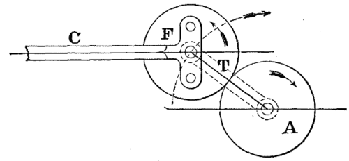
As another example of the difference in the application of these formulae, let us take Watt's sun and planet wheels, Fig. 19. This device, as is well known, was employed by the illustrious inventor as a substitute for the crank, which some one had succeeded in patenting. It consists merely of two wheels A and F connected by the link T; A being keyed on the shaft of the engine and F being rigidly secured to the connecting-rod. Suppose the rod to be of infinite length, so as to remain always parallel to itself, and the two wheels to be of equal size.
Then, according to Prof. Willis' analysis, we shall have -
| n' - a m' - a | = | n m | = -1, n' = 0, ∴ | -a m' - a | = -1, whence |
-a = a - m', or m = 2a.
The other view of the question is, that F turns once backward in its bearings during each forward revolution of T; whence in Eq. 2 we have -
| n' m' - a | = | n m | = -1, n' = - a, |
| ∴ | -a m' - a | = -1 which gives -a = a - m', or m' = 2a, |
as before.
It is next to be remarked, that the errors which arise from applying Eq. I. to incomplete trains may in some cases counterbalance and neutralize each other, so that the final result is correct.
PLANETARY WHEEL TRAINS. Fig. 20
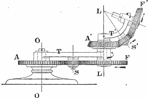
For example, take the combination shown in Fig. 20. This consists of a train-arm T revolving about the vertical axis OO of the fixed wheel A, which is equal in diameter to F, which receives its motion by the intervention of one idle wheel carried by a stud S fixed in the arm. The second train-arm T' is fixed to the shaft of F and turns with it; A' is secured to the arm T, and F' is actuated by A' also through a single idler carried by T'.
Continue to:


My Books

