Compound Microscopes. Part 3
Description
This section is from the "Histology of Medicinal Plants" book, by William Mansfield. Also see Amazon: Histology of Medicinal Plants.
Compound Microscopes. Part 3
Polarization Microscope
The polarization microscope (Fig. 20) is used chiefly for the examination of crystals and mineral sections as well as for the observation of organic bodies in polarized light. It can, however, also be used for the examination of regular biological preparations.
If compared with the regular biological microscope, the polarization microscope is found characteristic of the following points: it is supplied with a polarization arrangement. The latter consists of a polarizer and analyzer. The polarizer is situated in a rotating mount beneath the condensing system.
The microscope, of which the diagram is shown, possesses a triple "Ahrens" prism of calcite. The entering light is divided into two polarized parts, situated perpendicularly to each other. The so-called "ordinary" rays are reflected to one side by total reflection, which takes place on the inner cemented surface of the triple prism, allowing the so-called "extraordinary" rays to pass through the condenser. If the prism is adjusted to its focal point, it is so situated that the vibration plane of the extra-ordinary rays are in the same position as shown in the diagram of the illustration.
The analyzer is mounted within the microscope-tube above the objective. Situated on a sliding plate, it can be shifted into the optical axis whenever necessary. The analyzer consists of a polarization prism after Glan-Thompson. The polarization plane of the active extraordinary rays is situated perpendicularly to the plane as shown in the diagram. The polarization prisms are ordinarily crossed. In this position the field of the microscope is darkened as long as no substance of a double refractive index has been introduced between the analyzer and polarizer. In rotating the polarizer up to the mark 90, the polarization prisms are mounted parallel and the field of the microscope is lighted again. Immediately above the analyzer and attached to the mounting of the analyzer a lens of a comparatively long focal length has been placed in order to overcome the difference in focus created by the introduction of the analyzer into the optical rays.
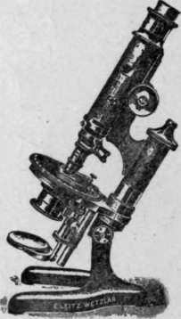
Fig. 20. Polarization Microscope.
The condensing system is mounted on a slider, and, furthermore, can be raised and lowered along the optical centre by means of a rack-and-pinion adjustment. If lowered sufficiently, the condensing system can be thrown to the side to be removed from the optical rays. The condenser consists of three lenses. The two upper lenses are separately mounted to an arm, which permits them to be tilted to one side in order to be removed from the optical rays. The complete condenser is used only in connection with high-power objectives. As far as low-power objectives are concerned, the lower condensing lens alone is made use of, and the latter is found mounted to the polarizer sleeve. Below the polarizer and above the lower condensing lens an iris diaphragm is found.
The microscope table is graduated on its periphery, and, furthermore, carries a vernier for more exact reading.
The polarization microscope is not furnished with an objective nose-piece. Every objective, however, is supplied with an individual centring head, which permits the objective to be attached to an objective clutch-changer, situated at the lower end of the microscope-tube. The centring head permits the objectives to be perfectly centred and to remain centred even if another objective is introduced into the objective clutch-changer.
At an angle of 45 degrees to the polarization plane of polarizer and analyzer, a slot has been provided, which serves for the introduction of compensators.
Between analyzer and ocular, another slot is found which permits the Amici-Bertrand lens to be introduced into the optical axis. The slider for the Bertrand lens is supplied with two centring screws whereby this lens can be perfectly and easily centred. The Bertrand lens serves the purpose of . observing the back focal plane of the microscope objective. In order to allow the Bertrand lens to be focused, the tube can be raised and lowered for this purpose. An iris diaphragm is mounted above the Bertrand lens.
If the Bcrtrand lens is shifted out of the optical axis, one can observe the preparation placed upon the microscope stage and, depending on its thickness or its double refraction, the interference color of the specimen. This interference figure is called the orthoscopic image and, accordingly, one speaks of the microscope as being used as an "orthoscope."
After the Bertrand lens has been introduced into the optical axis, the interference figure is visible in the back focal plane of the objective. Each point of this interference figure corresponds to a certain direction of the rays of the preparation itself. This arrangement permits observation of the change of the reflection of light taking place in the preparation, this in accordance with the change of the direction of the rays. This interference figure is called the conoscopic image, and, accordingly, the microscope is used as a "conoscope."
Many types of polarization microscopes have been constructed; those of a more elaborate form are used for research investigations; others of smaller design for routine investigations.
Continue to:
My Books

