The Boiler. Part 5
Description
This section is from the "The Construction Of The Modern Locomotive" book, by George Hughes. Also see Amazon: The Construction Of The Modern Locomotive.
The Boiler. Part 5
On marking the holes off in the throat plate, first try for levelness, then carry the vertical centre line round the flange, previously marked on the plate by the flanger, and cramp on the half template at D, Fig.23, which has been made the exact depth of the flange, making sure that the planed edge of the template is in the same plane as the inside of the throat plate. Mark the holes, and whistle this template is on, with a pair of reversers mark the first vertical hole for the joint with the outside or wrapper plate. From this hole fix the template for the vertical holes, and mark off the length upon each side; then place a straight-edge across E, Fig. 23, at these distances, and lay a square upon the centre line, the edge of the blade in the same plane as the edge of the straightedge, and try over with a pocket square, in order to ascertain that the holes and length are square with the centre line. By this means the rivet holes in the circumference, and the vertical ones for the wrapper plate, are bound to be square with the boiler. The centre lines of the rivet holes are then marked with a surface gauge, using either the inside of the throat plate or placing it upon parallel blocks, and marking from the surface plate.

Fig. 20.

Fig. 21. Scale ⅜" = 1 Foot.

Fig. 22.
Fig. 23.

Fig. 24.

Fig. 25.
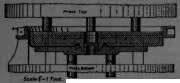
Fig. 26.

Fig. 27.

Fig. 28.

Fig. 29.

Figs. 30 - 32.
When marking the holes the back plate, it is first, tried over with a straight-edge, placed upon a surface plate, trammelled for the centre line, and this line carried round the flange. A whole template is then cramped on, and all holes marked for stays and mountings. The plates are then turned over, placed upon treaties, and a half-gauge cramped on for marking the rivet holes. This half-gauge - it has the same section as the wrapper plate - was drilled when straight, from the same template, and afterwards bent to radius, the same as the wrapper plate; so that the holes in the back plate must come in exactly with the wrapper plate. The half-gauge is made to the right length, and this is marked upon the plate for shearing. All half-gauges or templates are made in the same manner, so that with a system of templates thoroughly carried out, it is impossible to go far wrong, and the saving of time and wages is very great After annealing the flanged plates, the wrapper plate, the back and throat plates are bolted together and riveted, and the box is then ready for jointing to the barrel.

Figs. 33-35.
In jointing the casing to the barrel, Figs. 36, 37, it is first set square by means of the plumb bob A, utilising the original centre line marked for the flanger. The barrel is then bolted to the casing, being set by the aid of a spirit level, suitable packing being used to make up for the telescopic effect of the joints. The exact overall length is then determined, and B B' is cramped on to the weldless ring and the back plate; straight-edges are then placed across, and measurements are taken with a longitudinal straight-edge. This length is made minus ⅛ inch, because after riveting up the throat joint, and after the trial fire, the expansion will not completely recover itself by ⅛ inch. The outside diameter of the barrel at C, Fig. 36, being equal to the width between the frames, a line is thrown over, and then the strip D, equal to the width between the frames, is fixed to the back plate, giving a « - inch clearance upon each side of the fire-box. The strips E are then bolted to the weldless ring, and a line carried round the boiler C", just touching the line at C', and equally divided at D. After trying if the box is parallel on each side with the lines, and should it be found, say, ⅛ inch wide at F and 1/16 inch at G, that is, a small twist upon the box, a stretcher is fixed in tension at H, and the radius of the flange paened at F1, the same operation being repeated at the other corner for 1/16 inch, until the sides of the box are made parallel with the lines and square with the framing. This paeniug is avoided as far as possible, but it is almost ab-solutely impossible to entirely dispense with it. If the box is narrow, the stretcher should be in compression and the root paened inside. To maintain the level of the plate, the root should be the portion always paened. It is generally more difficult to set in, than set out. Repeated trials are made until the box is right, the length is tried over again, the joint firmly bolted, and then riveted, as in Fig. 10.

Fig. 36.
Fig. 37.
The boiler is now ready to be marked for the expansion angle iron, Figs. 36-38, and the longitudinal centre lines along the barrel. In this case the bottom edge of the expansion bracket is 2 feet 8 inches below the centre line of the boiler, and a gauge is first made, thus and then a straight-edge is fixed to the back plate at D, using the above gauge so that the top of the straight-edge is an exact parallel line with the cross centre line upon the back plate previously marked for the benefit of the flanger. The boiler is then levelled transversely. The radius of the barrel next the smoke-box is then ascertained, which is in the example before us 2 feet 1 inch, thus requiring a 7-inch packing between the bottom of the barrel and the plane of the expansion bracket, the radius of the third barrel-plate being 2 feet 2 inches, gives a 6-inch packing for K, Fig. 36, which packings are generally of hard wood. Straight edges are then bolted to these brackets which are capable of vertical adjustment, and then levelled, because the boiler has already been levelled transversely. Owing, perhaps, to a little twist in the boiler from riveting up the throat joint, these straight-edges may not be in the same plane. The boiler may be just a shade up or down at the smoke-box end, only a very little, which cannot be altered; consequently the middle straight-edge may be high or low, as the case may be - nothing to matter as a rule, otherwise there would have been a serious error. A line is carried from the firebox straight-edge to the smoke-box straight-edge, having the thickness of, say, two or three pieces of paper between it and the straight-edges, which gives a better chance of seeing if the middle one is in the same plane; then adjust, when the exact elevation or depression of the smoke-box end is ascertained.
Continue to:
My Books

