The Boiler. Part 4
Description
This section is from the "The Construction Of The Modern Locomotive" book, by George Hughes. Also see Amazon: The Construction Of The Modern Locomotive.
The Boiler. Part 4
The sides and top of the fire-box shell are made in one plate. The front, throat or saddle plate of the fire-box shell is flanged forward and double-riveted to the boiler. Figs. 6 and 11, The back plate is flanged to 6-inch radius outside, and single-riveted to the sides and top, Figs. 12 and 13; the upper part is stayed by a T girder. A steel casting, Fig. 14, is double-riveted to the inside of the plate. A similar stay is fixed to the inside of the smoke-box tube plate; also longitudinal stays, palm stays to the copper box, and other stays where shown on the drawings. The T iron for carrying the suspension links is also a steel casting, as well as the roofing stay bars, Figs. 15, 16 and 17. In dealing with the wrapper or outside fire-box shells, all the buckle is taken out, and then they are dealt with in batches of five, the same as the shell plates, every hole being marked on the template for drilling for the stays, expansion bracket, handrail, clothing studs, safety valve, roof bars, whistle stand, mud plugs, etc. After drilling, which has been done at a multiple drilling machine, with a lock upon the side of the machine to preserve the pitch accurately, they are marked, punched, sheared and planed in the same order as the barrel plates, and then taken to the plate bending rolls. The short sets to a radius of 6 feet are worked first, the plater working to the lines as shown on the sketch below.
Fig. 7.
Fig. 9.

Fig. 8.

Fig. 10.

Figs. 11-13.
Fig. 14.
The plate is then turned over and the crown radius bent, trying from time to time with the half gauge. When the machine, Fig. 8, has been used a number of times, this half gauge is not required very much, because of working the adjustable roll to previously worked-out marks. After bending, a stay of standard width is bolted between the sides to keep them from sagging the radius, and then they are taken to the drilling machine for the rivet holes between the frames to be countersunk. The foundation ring is a steel casting, shown in detail in Figs. 18,19 and 102, 102a. After annealing it is sent to the furnace, in order to have contraction defects removed, such as squaring-up and straightening. It may be that the ends are not at right angles with the sides; if so, all four corners are heated, and a stretcher is fixed across the opposite corners diagonally, drifting it out and "paening" the corners not drifted, until all four sides become square with each other. Afterwards it is sent to the grinders, then the rivet holes are drilled through a jacket or jig at a multiple drilling machine, and the other holes, such as the corner rivet holes and ash-pan studs, at a radial drill It is then sent to the smith's fire to get the flange plates thinned and set to the corners. It is contended by some well-known boiler-makers that locally heating a steel plate, thinning-down and hammering the corner to a bevel edge is a bad practice; consequently they use a specially designed plate-corner thinning machine, which thins off the corners very uniformly; but in this case the plate has to be punched thus otherwise the maker would have to be simply content with a single rivet, and therefore lose the benefit of the extra lap; whereas if drawn out they are simply sheared straight. Some firms slot a recess in the ring at the corners.
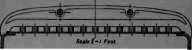
Fig. 15.

Figs. 16, 17.
A, bent to 6 feet radius. B, bent to 2 feet 3 inches radius (outsidel).

Fig. 18.
Fig. 19.
Generally speaking of flanging, it is preferable to have the flangers A, Figs. 20-29, cast in segments, frequently in halves, because they always get larger in use, and if cast thus, slack can be easily taken up by removing a ¬ - inch liner and substituting a ⅛ - inch. The flanging and vice blocks B C, Figs. 20-29, are cast in segments, which gives a certain amount of springiness, and if a block breaks it can readily be replaced by casting another segment; then the curves can be easily got up by fitters where it is not possible to turn them, the requisite amount planed off the strips left for this purpose, and the blocks then jointed together. In flanging the throat-plate, Figs. 20-25, the half template, Fig. 25, is first made, the centre line is marked down the plate to he flanged, the half template put on, marked, punched and sheared, leaving a little for trim-ming up after flanging, because it is possible that the plate may draw one way or another, and then sent to the flanging press. The press has three main press rams acting upon the press bottom, and four vice rams, which act independently of the main press rams through apertures in the press bottom. The press top is supported and the thrust received by four bolts, and is capable of being adjusted to the required height. The flanger A, Figs. 20, 21 and 22, is securely bolted to the press top, using suitable packing, the throat flanging block B to the press bottom, and the vice block C rests upon the vice c 2 rams. The plate is then got to a good red heat, placed upon the vice block, centre line for centre line; also the plate has two holes punched in it, Fig.23, to correspond with holes in the block, and steady pins are put in these to hold the plate in position as accurately as possible. The pressure is turned on the vice rams, by which operation the flange to the fire-box is formed. Whilst gripped in this position, the press rams come into operation, and the throat flanger B then forms the flange to the barrel plate. In flanging the back plate, Figs.26 and 27, motion is given to the vice rams, which forms the fire hole, and whilst holding the plate in this position, the main press rams are put into motion, forming the flange to the outside casing. The flanging of the smoke-box tube plate is similar in every respect to that of the back plate shown in Figs, 28 and 29, excepting the vice rams, which only hold the plate against the top block B whilst the flanger A does its work. The tube holes are drilled through a jacket at a multiple drilling machine, and the surface for the steam pipe flange is faced up. The finished plates and templates of the back plate and tube plate are shown in Figs, 30-35. After flanging, and contraction is over, the plate is set exactly to gauges and templates, all radii being made exactly right, the flanges squared up and the plates generally levelled. They are then marked for lap, punched and sheared, the corners thinned where required, and all holes marked for drilling.
Continue to:
My Books

