The Machine Shop. Part 7
Description
This section is from the "The Construction Of The Modern Locomotive" book, by George Hughes. Also see Amazon: The Construction Of The Modern Locomotive.
The Machine Shop. Part 7
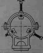
Each piston head is chucked and the cone bored. It is then fixed on a cone mandril, screwed tight up and placed between the lathe centres for turning the periphery and ring grooves. The rods are turned, also the eones at each end, to standard gauges, and then sent to the cotter-hole machine, which is a double headed slot drilling machine. The cross-heads, Figs. 80, 90, p. 89, are faced up on both sides, and bored out for the gudgeon by cramping to the face plate. They are then placed in the special chuck, Fig. 289, and rough turned, afterwards the stay, Fig. 290, is placed in position, and the cone bored and finished. The centre of the loose headstock is brought up to the cone, the stay removed, and the outside is finished. This stay is a useful appendage, and can be brought in for numerous jobs, both standard and emergencies. It only remains now for the edges of the cross-head to be milled.
The slide bars are planed all over, four at once, set in a special bracket attached to the table of the machine, at a speed of 18 feet to 20 feet per minute. They then go to a small slotting machine for the clearance to be slotted and to be cut to length, afterwards the holes are drilled, and then finished by glazing. The slide blocks are also planed, a quantity at once, the recess for the white metal, and also the oil grooves, being milled at a rapid rate.
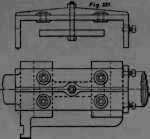
The rods and the rest of the motion in the ordinary course of events would have followed on here, but these were dealt with under milling and its operations, so that we must now pass on to the reversing shaft and radius links, and conclude with this class of work, The reversing shaft, Figs. 95, 97, p. 90, is first set out, then turned up in the middle and at the ends, after which it is slotted out to receive the radius links, which are put in a driving fit, being pressed by a. little mechanical device, and secured by two ⅝ inch set screws. The jacket for drilling these holes is shown in Fig. 291. The radius links, Fig. 236, p. 141, are first planed upon the back side, and then fifteen of them fixed upon a lathe face-plate, forming a complete circle of 3 feet 7« inch radius, and turned out to receive the slipper blocks, then faced up to the right thickness, and afterwards slotted to length and for clearance upon the flats to fit the reversing shaft. After thus finishing they are case-hardened all over, then the rubbing surfaces ground up in a vertical grinding machine, being fixed on the radius grinding table, Fig. 292, which is attached to the machine when required, and is capable of receiving a variety of articles of this description. The slipper blocks of phosphor bronze, Figs. 151 to 156, p. 110, are turned all over upon the same face plate, twenty-four forming the radius, or sometimes they are milled up, the radius being produced by a special device.
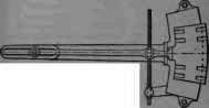
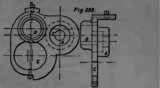
Fig. 292 Scale ⅝ = 1.0.
Fig. 293 is a boring jacket for opening out under a radial arm or ordinary drilling spindle, the dummy gland for the brass bushes in the front steam chest cover of engines having the steam chest between the cylinders. These jackets, jigs or rigs, are applicable to every repetition operation, whether turning, planing or drilling, and the illustrations given are a mere tithe of the host. They save time in fixing work on the machines, labour in setting out, and are certainly conducive to accuracy.
Brass finishing and its requirements are all concentrated in one portion of the shop, under one chargeman, who is responsible to the foreman. The appliances consist of lathes, which are chiefly capstan and chasing, suitable machines with fly-cutters for nuts, emery bands about 1« inches wide, glazing wheels, "buffs" for polishing, and cock grinding machines. The buffs are generally squares of calico, a number put together, the diagonals placed to form, as it were, a many-sided figure, which when revolved at a high rate, and a little flour of emery used, produces a good polish in any corner or intricate casting after it has been first passed over a circular brush, which also revolves at a high speed. These machines are placed in the order they are mentioned, so that when all work reaches the bench there is nothing to do but fix together and test. The only proposed illustration of work done of this class is the injector, winch is fully shown and described on p, 115, and by reference to those illustrations the details of the manner of work will he facilitated. It is actually an intricate piece of lathe work, requiring considerable skill and patience, as every one of the cones in the cone chamber is fixed in steam and water-tight, as well as the seating of the wing cone 2716, upon the top of the combining cone, 2714. These cones, which can be easily picked out on p. 118, are first dealt with by chucking in the lathe and boring out. They are then accurately finished by the group of boring bits, Fig. 294, which the reader can easily identify with each of the cones in Fig. 187, p. 116. These bits are carefully turned to the standard size, then they are backed to give clearance to the cutting edges, and as the quantity of material they have to remove is very small indeed, they last an almost infinite period. The outsides of the cones are turned by chucking them from the inside on lead chucks.
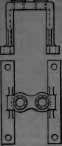
Fig. 293 Scale ¾ - 10.
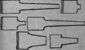
Fig. 294.
Meanwhile the main casting has been set out, and the flange for forming the junction with the boiler has been planed. The seatings and stuffing-boxes for the stop valve 2719, and the steam valve 2718, are bored by chucking this flange up against the face plate. The water and overflow cock seatings 2725, are bored by chucking the same flange to an angle plate attached to the lathe face plate. The next operation is to bore out, thread and face the seatings for the various cones in the central chamber. This is done first by chipping, filing or otherwise making even and circular a bevel where the cap 2711 enters, then fixing on the chuck or centre plate, Fig. 296, to the enlargement for the overflow union, and making the top edge parallel with the planed face of the flange. This plate has three centres fixed in, corresponding to the central cone chamber, back-pressure valve seating, and the ejector steam union, shown at A, B and C.
Continue to:
My Books

