Part II - Distribution Drums And Details Of Pressure Tests
Description
This section is from the book "American Plumbing Practice", by The Engineering Record. Also available from Amazon: Plumbing: A working manual of American plumbing practice.
Part II - Distribution Drums And Details Of Pressure Tests
Figure 4 is a diagram of the distribution tanks at C, Fig. 1. D and E are for cold water under street and tank pressure respectively, and F is for hot water under tank pressure. T is the roof tank.
Figure 5 is a diagram showing the connections by which either or both supplies may be put in service. In construction the rising lines were started at the basement floor about 12 feet above their connections with the sewer under the cellar floor, and a system of horizontal pipes connecting their bottoms, was connected to the house pump temporarily set up for the purpose. As each story in height was successively added to all the lines they were pumped full of water, which was allowed to remain there till another section was set and filled, and so on till when the final height of about 200 feet had been reached the bottom sections had been under a continually increasing pressure for perhaps six weeks. Then the City Inspector was called to inspect the work. This severe test was made in this manner by the contractors, Byrne & Tucker, for their own satisfaction and to facilitate the prompt discovery of any imperfection of material developed by the pressure, and it proved satisfactory to them.
Figure 6 shows the pump P connected up for the pressure test. B is its suction from a reservoir C supplied by independent connections D and E from the city mains on Dey and Cortlandt Streets respectively. The discharge pipe F delivers into systems of pipes supplied by G on the basement ceiling, and H H under the basement floor, which together connect as at K, Fig. 6, with all the vertical rising lines shown in Figs. 2 and 3. System G is formed of the drip and emptying pipes provided for the risers, though they are in some instances moved from their final permanent positions. Pipes H and H are permanent tank-pressure distribution mains, and S S are street-pressure mains. L is an emptying pipe.
Figure 7 shows the connection of test pressure pipe A to the riser lines D D D. A and B are here the permanent supply and riser lines for cold water and remain permanently as shown after pipes F F F are disconnected and the tee E is closed. Eventually lines D D D are continued to the sewer, and separate tests are to be made of these additional joints and those at the fixtures.
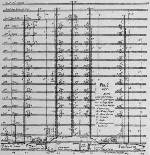


Figure 8 shows the method of connecting pressure test pipe T by screwing it into the cap C, which screws into wrought-iron riser R, and Fig 9 shows the method of connecting test pipe T to the cast socket S, which is calked on the cast-iron riser C.


Continue to:
My Books

