The House Drainage System. Part 3
Description
This section is from the book "A Working Manual Of American Plumbing Practice", by William Beall Gray, Charles B. Ball. Also available from Amazon: Plumbing.
The House Drainage System. Part 3
When both the connections are in vertical lines as in Fig. 147, after the water passes X, it will probably reverse the current of air in the fresh-air pipe in some instances; but, were it possible to shove out every atom of air in the soil pipe between the trap and point X, there still would not be a particle of foul air puffed out at the fresh-air opening, if the fresh-air pipe is of greater length than the distance between X and the trap.
After the fixture water reaches X connection when X is made in a larger and horizontal pipe, its interference with the air is not considerable. The object in not connecting the loop stacks as close together as fittings will permit when they lead into a horizontal line, is to keep the water, as it turns into the horizontal main, from interfering with the entry of air to the vent. By giving some distance to travel before reaching the loop connection, the discharge of water will be well spread in the main line before passing it. From this point on, it may cause violent eddying of the air in the main, but no actual reversal of the current will take place.
The force of air in front of water in down spouts that connect inside of the intercepting trap, may at times reverse the air in the fresh-air inlet proper. The loop pipe is an aid in this respect, too, as more air is at hand to cushion the rush of a sudden downpour; and the various fixture trap seals are, if affected at all, left much more stable. It would, if necessary, be better to have soil-pipe air expelled from an inlet, at times, by the action of storm water, than to incur the risk of siphonage or waving-out of fixture trap seals for lack of it.
No pipe of any building should open to the air with less than a 4-inch end. Small pipes should be increased to 4 inches before passing through the roof, as shown in Fig. 148. Pipe 4-inch and larger, up to 6-inch, should be increased to 6-inch. The object in all cases being to prevent closure by hoar frost. With 6-inch and larger pipe, it is doubtful if it is ever necessary to increase the size at the roof, excepting in buildings with cold roof space, no matter how high the building may be; yet some city ordinances call for an increase of one size regardless of size, which is manifestly foolish, as it permits increasing 2-inch to 2 1/2 or 3-inch on any type of job, and this is known to be inadequate in any but southerly latitudes. The velocity of air up the line is, of course, higher in tall buildings than in low ones; hence, in them, more moisture is carried through any given opening, and the theory of increasing large pipe at the exit is based on the assumption that smaller openings would, as a result of this excess of moisture,
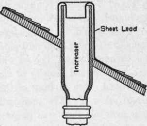
Fig. 148. Vent Pipe Increased in Size.
Before Passing through Roof, to be closed by frost. The great amount of warmth over large buildings must often, however, be considered as reducing the chances of closure by hoar frost. In tropical climates, no increase of any size is necessary. In southerly temperate latitudes, no special attention is given precautions against hoar frost, beyond increasing the size of small vents to at least 4 inches in diameter.
Prevent Closure by Hoar Frost.
Flashings. There are patent devices for flashing around pipes, usually made of copper; but the plumber will do well to command the skill necessary to manipulate sheet lead to suit conditions as he finds them. In any location where warm air will always be seeking an outlet from the attic through chance openings, the sleeve of the flashing may be made two to four inches larger than the outside diameter of the vent, and capped with an annular V-ring of lead in the manner shown in Fig. 149. The cap ring need only be tacked to the sleeve with solder. The top edge of the sleeve should be notched or some other provision for air-exit made, so as to insure constant changing of the air in the sleeve. If, on account of braces or projections necessary to hold the pipe rigid where it passes through the sheeting, it is inconvenient to let the sleeve extend below the sheeting as shown in the engraving, it may terminate at the roof line. If the building is a storage warehouse, or for any reason the attic will not be very warm, or conditions are in favor of cold air being drawn in through chance openings in winter, then the method of flashing and packing the sleeve with felt or mineral wool as shown in Fig. 150 should be employed. In all cases the vent and flashing must rise above the possible snow-level for flat roofs. The snow-level on a steep roof will be less, but drifts may obstruct the vent if left at the snow-level. Some latitude for settling of the roof under the weight of snow and ice, and for expansion of lines supported by brick piers or other supports far below the roof-level must be allowed in fitting flashings. If they are too closely drawn or capped, trouble will soon follow.
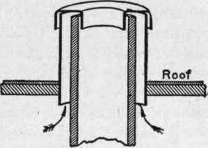
Fig. 149. Pipe Flashing Capped with V Ring of Lead and Providing Egress for Warm Air from Attic.
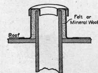
Fig. 150. Pipe Flashing Packed with Felt or Mineral Wool where it is Desirable to Conserve Warmth in Attic..
To develop the pattern for a tapering sleeve for a vent for a flat or nearly flat roof, draw, as in Fig. 151, XY at random; set off AB equal to the altitude of the sleeve; then AC from A, perpendicular to AB; then BD from B, parallel to AC; let AC equal half the diameter of the sleeve at the top, and BD half the bottom diameter; then cut CD with a line crossing XY. Lines AC, CD, DB, and BA now outline half the elevation of the sleeve at the center. Next, with the intersection of XY and CD projected (X in the diagram) as a center, describe the arcs EF and GH. On EF, set off the circumference of the base of the sleeve JK (twice BDX 3.1416 equal circumference, which is equal to 6 radii or 6 times BD stepped on arc EF with the dividers), and then indicate JX and KX. This develops the net pattern, and it remains only to add the necessary working edges to get, when cut out and formed up, a sleeve of the exact shape and dimensions required. The development of a tapering sleeve for a pitched roof by strictly geometrical methods, is so intricate, and the springs and pitches of roofs so varied, that the plumber usually ignores - and is generally sensible in doing so - the true methods of cutting out such flashings. Lead is pliable, and flashings for pitched roofs can be roughly laid off as follows, and then worked and trimmed to suit. The circumference and curvature of the top edge and lines of the ends can be joined, are obtained by full-size diagrams in the same way as for a sleeve for a flat roof, shown by Fig. 151. The circumference of the top edge is, in this case, set off on GH, because the bottom, corresponding to JK, is unknown. The elevation ABCD is made just as though a sleeve was to be made for a flat roof, with the tapering side equaling CD, Fig. 152, which should be laid out to represent the elevation of the sleeve desired. The pattern diagram (Fig. 151) should be so drawn as to throw line XCD about the center or neck of the pattern, so as to bring the seam on the low side and thus present solid metal to the flow of water down the roof. The line of dots marked Z in Fig. 151, approximately outlines the bottom of the pattern, though the actual curves would be more or less pronounced, according to the pitch of the roof. The cross-mark guides by which to draw the bottom of the flashing, are seldom more than five in practice, and their positions are determined in this way: JX and KX of the pattern diagram are extended and set off from the GH line, Fig. 151, equal to XK, Fig. 152. This gives the actual seam length for the low side of the flashings, as would be indicated if XJ and XK, Fig. 151, were actually extended, to cut the extremes of the guide line Z. CD of both the elevation and pattern diagram being equal, CD, Fig. 151, equals the length of sleeve in the neck or upper side. For the length of sleeve at the sides, half way between the neck and seam, produce dotted line K1 Y, Fig. 152, parallel to CX, to a point where it will intersect the roof-plane at the center of the pipe space. KlX will then be equal to the required side lengths of sleeve, and may be set off on the pattern diagram by projecting radii from X, cutting the pattern midway between C and the seam lines, and setting off the distance XK1 on these radii, measuring from the GH line. These points are sufficient for approximating the bottom contour generally. When formed up, the bottom edge can easily be snipped into a plane.
Continue to:
My Books

