Types Of Water Supply. Part 3
Description
This section is from the book "A Working Manual Of American Plumbing Practice", by William Beall Gray, Charles B. Ball. Also available from Amazon: Plumbing.
Types Of Water Supply. Part 3
Fig. 63 shows the lining in place, and the method of applying the brace and straight-edge to the seams that are to be blown upright in position. Letters and parts in Figs. 62 and 63 correspond, N in Fig. 63 being the bottom.
Unless the supply is regular and abundant, and the storage by gravity, outside tanks of ordinary capacity, if of wood, are expensive and troublesome from leakage due to shrinkage of staves above the water-line and from necessity of painting; if of iron, from change produced in the character of the water, and, freezing; cost of boxing, delivery to, and discharge from, in a frost-proof manner, etc., are common to all forms of outside overhead tanks.
A spring supply will answer if high enough to store by gravity; or a waterfall above or below the house level may be handled with a hydraulic ram if 5 to 15 per cent of the available water will suffice.
Hydraulic Ram. A ram uses the energy of a fall to elevate part of the water passing through it - one-sixth or less, according to the fall and the height to which the water is to be delivered. Four feet of fall is about as little as can be utilized to advantage; and fifty feet of liberal-size drive-pipe, even though it has to be coiled with uniform fall, is necessary to give the water momentum enough to get the best results.
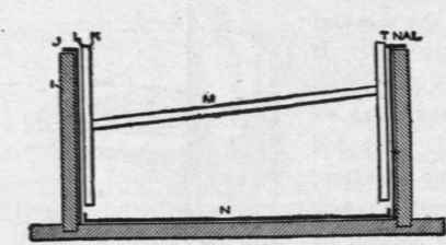
Fig. 63. Section Showing Lead Lining in Place, and Method of Bracing for Making Upright Seams..
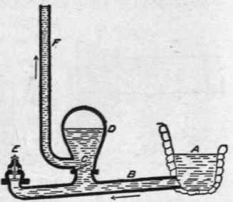
Fig. 64. Illustrating Principles of the Hydraulic Ram.
Fig. 64 illustrates the elementary principles of a simple Tarn. A represents the source or spring; B, the drive (supply) pipe; C, a valve opening upward; Z), an air-chamber; E, a valve tending to close downward by gravity; and F, the discharge pipe. Inaction, the water passes through the ram and out at a waste valve E, which is open downward until sufficient velocity is attained to lift it and close the waste exit. There being then no other means of egress, the check-valve C, opening upward to the discharge pipe, is forced open; and the energy of acquired momentum delivers water into the air-chamber D and discharge pipe F, until the pressure on the waste valve falls too low to hold it up (closed). The check-valve C then closes, and retains the water in the discharge; and the waste valve E falls open by gravity, leaving a comparatively unrestricted exit through which the water continues to waste with increasing force until the velocity in the drive pipe is again sufficient to repeat the impulsive delivery. Rams are made with large air-chambers, to cushion the initial strain of impulse, and should have a delivery pipe at least one size larger than the ram opening, especially if working under light fall or high delivery.
Cisterns are seldom so deep or situated so low that ordinary house force-pumps within doors cannot be used. The distance of the cylinder above the lowest level from which water may need to be pumped, is limited in all pumps alike - 33 feet 9 inches atmospheric lift under perfect conditions, and about 25 feet under the most perfect practicable pump arrangement. Indeed, the velocity of flow into the cylinder at any point above 20 feet is so slow that in practice the cylinder should be well within a twenty-foot limit in vertical distance from the water; and the closer the better. A foot-valve strainer at the end of a cistern suction pipe will keep the pipe filled and avoid frequent exhausting of the air before water can be obtained. When a foot valve is used, means of draining the suction to below frost line, when necessary, must be provided.

SECTION OF SWIMMING POOL SHOWING WATER HEATER AT THE RIGHT OF POOL WALL.
Courtesy of Fcdcral-Huber Company, Chicago
Continue to:
My Books

