


Lavatories. Part 2
Description
This section is from the book "Improved Plumbing Appliances", by J. Pickering Putnam. Also available from Amazon: Improved Plumbing Appliances.
Lavatories. Part 2
It is, nevertheless, still in many respects imperfect, and further modifications are necessary.
Although the stand-pipe is far easier to keep clean and bright than the discarded chain, still the metallic surfaces, both of the stand-pipe and of the surrounding outlet fittings, demand considerable attention and labor. Although they will never become black and foul like the chain, they will, nevertheless, ultimately lose their original lustre, as, indeed, is the case with all plated metal work.
To avoid this, and obtain an appliance which shall always retain its original brightness without care, forms the final step of our improvement.
Beginning with the stand-pipe, to avoid at once all burnishing and consequent wearing away of surface, we substitute for the metal glazed earthenware. The new material demands, of course, new treatment and connections. A soft washer must be used to form its seat, for the purpose both of taking off the jar of its closing and of forming a water-tight joint. The pipe is thickened to give greater strength, and is provided with a small brass wire passing through its center, and secured to the earthenware by simple cross-bars at each end. The lower cross-bar serves also to hold the washer on the stand-pipe, and the upper is provided with an eye, through which the hook of the lifting mechanism is passed to operate it. A prolongation of the wire passes through the strainer below and forms a guide for the stand-pipe.
Figs. 45 and 46 explain the construction.
As glazed earthenware is the most suitable material for the basin, so is it the most suitable for its stand-pipe. As it is cheaper than brass, non-corrodible and harmonious in color and texture with the basin, this modification enhances at once the economy, durability and appearance of the apparatus. The walls of the stand-pipe are nearly as thick and strong as those of the basin, and, standing within the shelter of the niche and under the protection of the marble slab, it cannot be broken in usage. Anything carelessly dropped into the fixture might crack the basin, but could not hurt its stand-pipe.
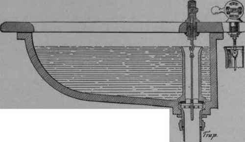
Fig. 45. - Final Step. The "Sanitas" Basin - Sectional View.
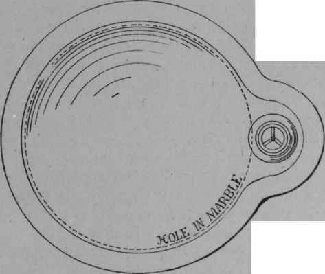
Fig. 46. - Plan.
To do away with metal in the walls of our stand-pipe is, however, not all that is necessary. The broad flange of plated metal at the outlet below the stand-pipe must also be excluded, for it presents, in its usual tarnished and marred condition, a very unsightly appearance. This may be avoided by sinking the metallic outlet fittings entirely below the surface of the basin and constructing them in the manner shown in the drawing. No metal work is now visible below the top of the stand-pipe when the outlet is closed, as it is covered by the projecting base of the stand-pipe, and nothing comes in contact with the water but glazed earthenware, and all parts of the apparatus are always clean and inviting. The lifting device is also susceptible of further improvement. In the construction shown in Fig. 44, the working parts are exposed in an undesirable manner, and the friction on the exposed wearing surfaces soon destroys the plating and mars the appearance. These surfaces might be constructed of a different metal from the rest of the mechanism, as, for instance, of German silver or of nickeline. This was actually tried, but the increased cost and difference of color still proved to be serious objections. Another defect in the arrangement was found to be the large amount of space it occupied on the slab, which prevented its use in contracted spaces where the slab was required to be narrow. There is, moreover, nothing in the design of either of the lifting devices above described to suggest to the user their mode of operating, and they are not sufficiently simple.
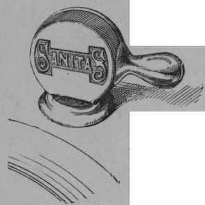
Figs. 47, 48 and 49 show the manner in which these defects have been removed. The apparatus consists of the simplest form of crank and of a small metallic case to support and protect it. The crank or lever consists of a disc supporting a pin and forming an oscillating back of the case. The pin lifts the stem of the stand-pipe. How shall the form of the device be made to suggest its mode of operation? It is done by placing the handle unsymmetrically with relation to the body so that the natural impulse shall be to reverse its position, and that such rever salshall open or close the outlet.
The handle stands horizontal on one side of the case when the outlet is closed, and on the other side when it is open, as shown in the figures. If the position of the handle were symmetrical, say, for instance, central over the case, and standing perpendicular when the stand-pipe were in either of its extreme positions, there would be nothing to suggest whether it should be moved laterally, perpendicularly or spirally, and the practical result would be a much quicker deterioration of the mechanism, especially with a new article and in public places, than if the correct handling were always assured. The plane of rotation of the handle is parallel with the front of the basin slab, so that the minimum of space is required and the shape and size of the slab are independent of it. Fig. 50 shows in perspective the manner in which the stand-pipe covers the metal work of the outlet, and explains clearly the arrangement of the lifting mechanism and its connection with the stand-pipe.
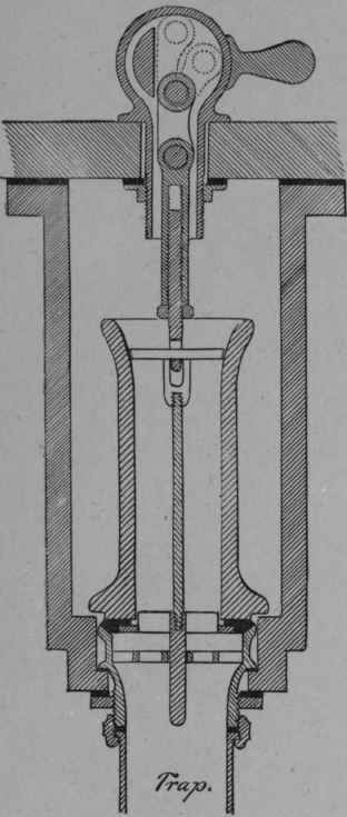
Fig. 47. - Detail of Lifting Mechanism. Section through Niche.
Continue to:


My Books

