Cocks And Valves
Description
This section is from the book "Principles And Practice Of Plumbing", by John Joseph Cosgrove. Also available from Amazon: Principles and Practice of Plumbing.
Cocks And Valves
Gate Valves
The two principal types of valves used to stop the flow of water in water supply systems are gate valves and globe valves. A gate valve is shown in section in Fig. 80. It is operated by raising and lowering the double-faced wedge-shaped gate, a.
When the valve is closed, the two faces of the gate are tightly pressed against the seats, b b, thus effecting a double seal. The chief advantages of a gate valve are its tight seal and full size straightway opening, which offers no greater resistance to the flow of water than would an ordinary pipe coupling or other fitting of equal length. Either end of this make of gate valve may be used as the inlet, although there are some makes of gate valves that are single seated or have only one gate face. Such valves should be screwed on a pipe with the valve face to the pressure.
Globe Valves
The type of valve most commonly used for water supply systems is the globe valve, shown in section in Fig. 81. This type of valve has an inlet and outlet end, and a valve disk, a, that closes against the pressure. The valve is operated by lowering the disk, a, until it presses firmly and evenly on the valve seat, b, and thus cuts off the flow of water. By turning the valve stem to the left, thus raising the valve disk from its seat, the water is turned on. Instead of an interchangeable soft disk, as shown in the illustration, some globe valves have a brass disk that closes on a brass seat. Such valves seldom remain water tight more than a few months and cannot be repaired as easily and inexpensively as can soft disk valves; therefore, it is a matter of economy to use soft seat valves. The principal objections to the use of globe valves are, that the opening, c, through the seat of the valve is never the full area of the corresponding size of pipe, and therefore not only restricts the flow but offers considerable frictional resistance; furthermore, the opening is not straightway, consequently it offers additional frictional resistance to the flow of water. In addition to the frictional resistance and loss of flow caused by globe valves, they also, when placed on horizontal pipes, form traps that keep the pipes half full of water when the pipes are drained. This is shown by the part, d, which shows the depth of water retained by a globe valve when the water is drawn off from the system. This latter objection, however, can to a great extent be overcome by turning the valve on its side, so the stem will be nearly horizontal. In this position the opening in the valve seat is as low as the bottom of the pipe and permits all water to drain out.
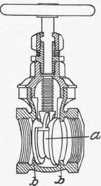
Fig. 80
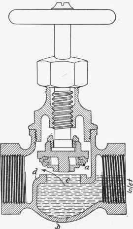
Fig. 81
Angle Valves
A type of valve much used for controlling the water supply to separate fixtures is shown in Fig. 82. It is known as an angle valve and is a modification of the globe valve. The openings to an angle valve are at right angles to each other so that the valve can serve the dual purpose of controlling the water and changing the direction of the pipe. Angle valves are made with metal seats and with seats of soft materials, the latter being the better kind for use on water supplies.
Lift Check Valves
A check valve is an automatic valve that opens to the pressure of water on one side but closes tightly when pressure is applied to the opposite end of the valve. Where it is necessary that water should always flow in one direction and there is a possibility of a reverse flow, a check valve should be used. There are two common types of check valves; lift check valves, and swing check valves. A lift valve is shown in section in Fig. 83. In this type of valve the check, a, seats by gravity when pressure in the system on both sides of the valve is equal. When pressure on the inlet end of the valve exceeds that in the outlet, as for instance when a faucet is opened, the pressure unseats the check, a, from the seat, b, and permits water to flow through the valve. If on the contrary there is an excess of pressure on the outlet end of the valve, the pressure will the more tightly seat the check and prevent any water from passing back through it. Check valves are made both for vertical and for horizontal pipes.
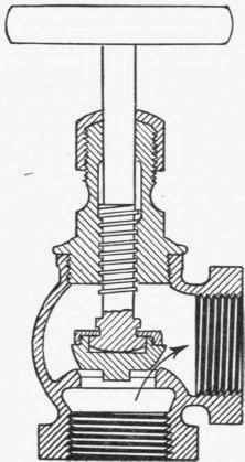
Fig. 82
Swing Check Valve
A valve of this type is shown in section in Fig. 84. It derives its name from the fact that the metal flap, a, yielding to the pressure of water, swings on the pivot, b, and thus presents a straightway opening for the flow of water. This type of check valve compares with the lift check valve about as a gate valve compares with a globe valve. The swing check valve offers less resistance to the flow of water through it and has a straightway opening of almost the full size of the valve. In the lift check valve, on the contrary, the water must pass through a reduced opening in the valve seat and must make two right angle turns while doing so.
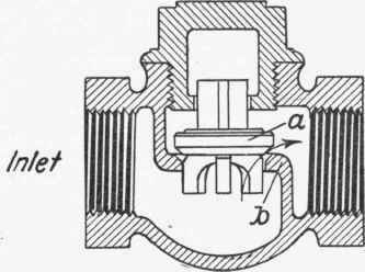
Fig. 83
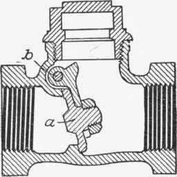
Fig. 84
Continue to:
My Books

