Faucets
Description
This section is from the book "Principles And Practice Of Plumbing", by John Joseph Cosgrove. Also available from Amazon: Principles and Practice of Plumbing.
Faucets
Fuller Pattern Faucets
A very good type of faucet for low pressure work is shown in section in Fig. 87. This type of cock is quick closing and closes with the pressure, a rubber packing, a, effecting the seal. On account of the quickness with which this kind of cock can be closed, each supply pipe to which they are connected should be provided with an air chamber and they should not be used on high pressure work.
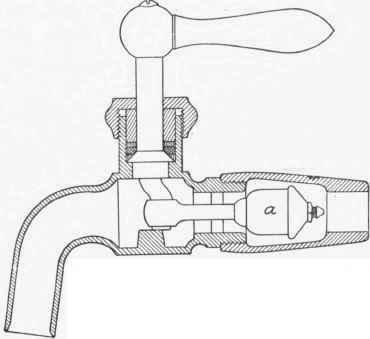
Fig. 87
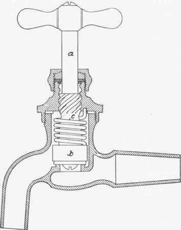
Fig. 88
Self-Closing Faucets
In localities where water is scarce, or where through carelessness in those who use the fixtures much water will be wasted, it is customary to fit all fixtures with self-closing faucets. Water can be drawn from a self-closing bibb only while it is held open; the moment the hand is removed, the faucet is immediately closed by a spring provided for that purpose. A self-closing sink faucet is shown in Fig. 88. When the stem, a, is turned to the left it raises the block, b, thus compressing the spring, c, which, as soon as the pressure is removed, returns to its original shape, thus closing the faucet.
Pressure Regulators are apparatus for controlling or decreasing the pressure of water within a building and thus relieving the system of excessive strain. By their use, the static pressure within a building can be maintained at a pressure of 15, 25 or more pounds, while the static pressure in the street might exceed 100 pounds; at the same time, the volume of water or the pressure of the water while running will not be affected by the pressure reducing valve. The principle of operation of a pressure regulator can be explained by a reference to Fig. 89. The area of the valve seat, a, bears a certain relation (say one-fourth) to the area of the disk, b; consequently, with a pressure of 100 pounds per square inch in the service pipe, c, the valve, a, will seat when the pressure in d exceeds 25 pounds. This is owing to the greater area in b, which compensates for the greater pressure acting on the less area of a. The pressure in d at which the valve seats, or in other words, the amount of pressure to be carried in the water supply system, can be regulated by adjusting the fulcrum, e. Moving it to the right will increase and moving it to the left will decrease the pressure in the system.

Fig. 89
A sectional illustration of a pressure regulator extensively used in practice is shown in Fig. 90. In this regulator two pistons, called cups, of different areas are used instead of the two discs in the former illustration. The operation of the valve is as follows: When water is admitted to the pressure side of the regulator, it passes through the valve port and fills the system of piping on the house side; as soon as the system of piping is filled, the back pressure acts on the upper cup and tends to raise the stem and thus close the valve. As the area of the upper cup is greater than that of the lower cup, a less pressure per square inch is required on the low-pressure side to exceed the pressure exerted on the lower cup on the high-pressure side; consequently, when the pressure on the house side exceeds a certain percentage of the street pressure, the valve will close. As soon as a faucet on the house side of the regulator is opened, it lowers the pressure on that side, and the high-pressure acting on the lower cup will again open the valve.
The area of the low-pressure cup bears a certain ratio to that of the high-pressure cup, consequently, if provision were not made to overcome the difference between the force tending to close the valve and the force tending to hold it open when the pressure on both sides is equal, it would be impossible to maintain a pressure on the house side of the valve greater than that due to the ratio between the two cups. For instance, if the ratio of area of the high-pressure cup to that of the low-pressure cup were one to four, and the pressure on the street side were 40 pounds per square inch, the valve would close when the pressure on the house side exceeded 10 pounds per square inch and no higher pressure could be maintained. To overcome this difficulty a spring, a, and tension screw, b, are provided. Turning the screw to the right increases the tension of the spring against which the low pressure must act to close the valve, and, in proportion as the tension screw is screwed down, the pressure on the house side of the valve will be increased.
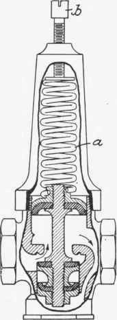
Fig. 90
There is a limit to the reduction of pressure possible to obtain by means of a pressure regulator. This reduction depends to a great extent on the pressure of water on the street side of the valve. For instance, the lowest pressure it is possible to obtain for 40 pounds pressure is about 14 pounds; 50 pounds pressure, 16 pounds; 60 pounds pressure, 18 pounds; 70 pounds pressure, 20 pounds; 85 pounds pressure, 21 1/2 pounds; 100 pounds pressure, 23 pounds; 115 pounds pressure, 25 pounds; 125 pounds pressure, 27 pounds; 135 pounds pressure, 29 pounds; 150 pounds pressure, 31 pounds; 175 pounds pressure, 35 pounds; 200 pounds pressure, 39 pounds.
On account of the weight of the stem and the friction of the moving parts, it is impossible to obtain as low a reduction as zero, but any pressure between the two extremes mentioned can be secured by adjusting the tension screw on top of the cap.
A relief or safety valve should always be used in connection with a pressure regulator, to provide relief to the system should excessive pressure be generated by the water heating apparatus.
Continue to:
My Books

