Force Pumps
Description
This section is from the book "Principles And Practice Of Plumbing", by John Joseph Cosgrove. Also available from Amazon: Principles and Practice of Plumbing.
Force Pumps
Suction pumps are limited in the height to which they can deliver water by the atmospheric pressure at the elevation where they are installed; furthermore, they cannot be used to circulate water through a closed circuit. Hence, when water must be elevated a considerable distance through closed pipes, as, for instance, in filling a house tank, a force pump must be used.
A simple hand force pump is shown in Fig. 98. It combines the functions of a lift pump with that of a force pump. Water is raised to the cylinder by suction as in a lift pump, but when the solid piston, a, descends, the confined water cannot escape to the top of the piston, as in the case of a suction pump, but is forced out through the valve, b, to the house tank or other place of supply. This pump is known as a single stroke pump, as it lifts and forces with each alternate stroke of the piston.
Slip
At the end of the up stroke of the piston, the moment when it begins a down stroke, there is a brief interval of time during which both valves b and c are open, and during that time water flows back to the source of supply. This back flow of water is known as the slip of a pump. It increases with the height of the lift of the suction, the height to which the water is forced and the slowness of the valves in seating. When the vertical lift of a pump is small but the suction is long and the pump forces against a low head, the momentum of the moving column of water sometimes carries it forward while both valves are open; such a flow is known as the negative slip of a pump. The slip of a pump is a limiting factor in its capacity; when the slip is great the capacity of a pump will be correspondingly decreased, and when the negative slip is great the capacity of the pump will be greatly increased over its theoretical capacity.

Fig. 98
Air Chambers
When a force pump is operated it alternately sets in motion and brings to rest the entire moving column of water. As water is practically incompressible, the sudden starting and stopping of the column will cause water hammer that is both annoying to occupants of a house as well as damaging to the pump and pipes. This water hammer can be practically overcome by using an air chamber on the discharge pipe and so locating the air chamber that it will remain full of air and receive the initial impulse of the water. An air chamber not only prevents water hammer but also equalizes the flow between strokes of the piston. On large power pumps an additional air chamber should be placed on the suction pipe close to the pump. When pumps are operating under high pressures the air is soon absorbed from the air chambers which are thus rendered useless unless some means are provided for recharging them. A simple contrivance for charging air chambers of steam pumps is shown in Fig. 99. The air chamber and water cylinder of a pump are connected together through a gate valve, a, pipe, b, and a check valve, c, that opens towards the air chamber. Another check valve, d, that opens towards the pump is screwed to the pipe as shown. The standpipe, b, stands partly full of water. Then with the valve, a, properly throttled, when the water piston, e, makes a stroke to the left, some of the water will be drawn into the cylinder, and air will enter check valve, d, to take its place. On the reverse stroke of the piston, water is forced into the pipe, b, and as the confined air cannot escape through the check valve, d, it is forced into the air chamber thus keeping it charged.
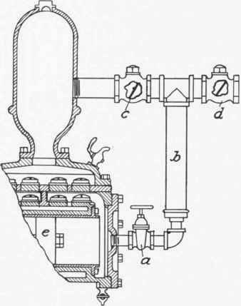
Fig. 99

Fig. 100
Continue to:
My Books

