Measurement Of Water
Description
This section is from the book "Principles And Practice Of Plumbing", by John Joseph Cosgrove. Also available from Amazon: Principles and Practice of Plumbing.
Measurement Of Water
Types Of Water Meters Velocity Meters Classification
The quantity of water flowing uninterruptedly through a pipe may be approximately determined either by calculation or by measurement. When the flow of water is intermittent, however, the quantity can be determined only by measurement. The manner of determining the flow of water by calculation has already been explained. It is measured by means of an apparatus called a water meter.
Water meters may be divided into two general classes: Velocity or inferential meters, and volume or positive meters. Velocity meters measure the velocity of water passing through them, and, the size of the discharge orifice remaining constant, the velocity per foot equals a certain quantity which is automatically computed and indicated on an index dial. Volume meters measure the volume of water passing through them and automatically register the quantity on an index dial; they operate by alternately filling and discharging a chamber of known capacity.
Venturi Meter
The simplest form of velocity meter is the Venturi meter, Fig. 68. This meter may be had in sizes ranging from 2 inches to 60 inches in diameter, and fitted with an index dial, a recording register, or with a manometer gauge, a, which simply indicates the rate of flow. The meter operates on the principle that when water flows through a contraction in a tube of the shape and relative cross sections of a Venturi meter tube, there is a temporary reduction of pressure at the throat b, which is approximately proportional to the square of the velocity. This reduction of pressure at the throat causes an unequal pressure in the pressure pipes c and d, which are connected respectively to the pressure chamber e on the inlet end of the tube and the pressure chamber f at the throat of the tube. This unequal pressure depresses the mercury in the leg g of the manometer and causes it to rise correspondingly in the other leg; a properly graduated scale showing the difference between these two mercury levels, indicates the velocity of flow through the meter. Having the velocity of flow and knowing the area of cross section of the meter, the quantity of water passing through in a given time can be calculated by multiplying the velocity for that period of time by the cross sectional area of the meter tube.
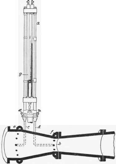
Fig. 68
The Gem Meter, Fig. 69, clearly illustrates the construction and principle of operation of a mechanical type of velocity meter. Water enters the cylinder from below and in rising presses against the propeller blades a, causing them to revolve in direct proportion to the velocity of the water flowing through the meter. The speed of the propeller is so adjusted that a certain number of revolutions equals a certain number of gallons or cubic feet which are automatically indicated on an index dial.
Continue to:
My Books

