Self-Siphonage Of Traps
Description
This section is from the book "Principles And Practice Of Plumbing", by John Joseph Cosgrove. Also available from Amazon: Principles and Practice of Plumbing.
Self-Siphonage Of Traps
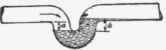
A trap can lose its seal from self-siphonage only when the waste pipe from the trap to the stack is unventilated and extends below the bottom level of the dip a of the trap so as to form the long leg of a siphon (Fig. 28). If the waste pipe extends directly back to the main stack, as shown in Fig. 29, without dipping below the bottom of the dip, the trap could not be self-siphoned because there would be no long leg, and, provided no fixtures discharged into the stack above where the waste connects, no back vents would be required for the trap.
Fie. 20

Fig. 27

Fig. 28
Loss Of Seal By Momentum
Theoretically, a trap may lose its seal by momentum. If a trap is placed directly beneath a fixture, but some distance below it, a flush of water might acquire sufficient momentum to carry it through the dip of the trap and into the waste pipe beyond. As a matter of fact, however, there are modifying conditions to prevent such loss. Most fixtures as now made have outlets so obstructed by strainers or cross-bars that the outlets are of less area than that of the waste pipe, consequently the pipe could not fill full bore and the velocity would hardly be sufficient to acquire the necessary momentum. If it did, no harm would result, as sufficient water would adhere to the long inlet pipe and to the sides of the fixture to again seal the trap. Nevertheless, traps should be placed as close to fixtures as possible, not only to prevent possible loss of seal by momentum but also to avoid a long stretch of untrapped waste pipe.
Siphonage By Aspiration
When unvented siphon traps are used, a trap on one floor of a building may be siphoned by water discharged into the. stack from a fixture at a higher level, as shown in Fig. 30. This is called siphon-age by Aspiration. The water discharged into the stack at the higher level, in passing the branch to the fixture at the lower level, creates a partial vacuum in the branch waste pipe that causes the water to be forced from the trap into the stack.

Fig. 29

Fig. 30
Continue to:
My Books

