Form Details And Practical Designs
Description
This section is from the book "Practical Concrete Work for the School and Home", by H. Colin Campbell. Also available from Amazon: Practical concrete work for the school and home.
Form Details And Practical Designs
Plate 1 illustrates some important details of form construction. The types of forms illustrated are simple. At the upper left-hand of the plate is shown a form with square ends made up of the four sides a. When the sides are withdrawn or removed from the object in the direction of the arrowheads there is no possibility of binding. Pieces a may be wider than the object is high and the mold filled only so full as necessary to come to the top of the object. In that way lumber need not be cut unnecessarily nor wasted.
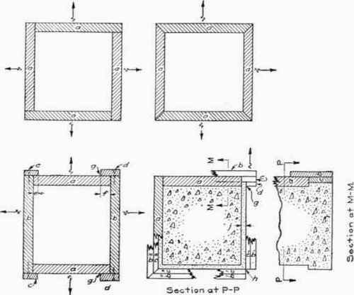
At the upper right-hand portion of Plate 1 is a form composed of four sides, assembled by having the pieces a mitered at their ends. This type of form requires a little more care in making in order that the miter be cut true. The use of forms of this kind is usually confined to concrete objects that have projecting surfaces which would prevent the sides a from being- withdrawn or removed in the direction of the arrowheads.
At the lower left-hand portion of Plate 1 are various details of a form with squared ends composed of the sides a and b. Sides b have cleats c and d nailed to their ends. These serve to hold sides a securely in position while concrete is being placed. Cleat c should not overhang or project beyond side a any more than necessary. It should have a good bearing surface on side a. This will permit withdrawing side b in the direction of the arrowheads with the least amount of binding or sticking due to swelling of the wood when the parts are wet. If the overhang of cleat c is as great as shown in cleat d greater difficulty will be experienced in withdrawing side b because of this large overhang as shown at g and f.
At the lower right-hand portion of Plate 1 is a form illustrating a case where it is sometimes necessary to use a combination of squared ends and mitered joints. As shown, the upper part consists of four sides a. The lower portion of the form consists of pieces c and d which are nailed together while the piece b is nailed to piece a. If mitered joints were not used at the lower portion of this form it would take the shape as shown in the upper right-hand corner of section P-P. The part d would have to be nailed to parts c and b in order to secure the required surface finish at g. Such a form when withdrawn in the direction of the arrowhead would bind on the object at g and would be difficult to withdraw without injuring the corners of the concrete. This, however, could be overcome by cutting off the ends of the pieces b and c as shown in the lower left-hand corner of section P-P with pieces b' and c' meeting at the corner and leaving the open space h. This arrangement would form a true edge for the concrete product and the forms could be removed without difficulty. However, unless the joint at h were tight it would allow water carrying cement to leak out of the form. To prevent this, pieces b and c are carried out and mitered as shown at b" and c" at the lower left-hand corner of section P-P. Mitered joints should be used in every case where there is even a slight projection beyond any one surface of the concrete object.
Continue to:
My Books

