Chapter VI. Plumbing
Description
This section is from the book "Mechanics Of The Household", by E. S. Keene. Also available from Amazon: Mechanics Of The Household.
Chapter VI. Plumbing
The term plumbing is usually understood to cover all piping and fixtures that carry water into the house and remove the waste material in the form of sewage. It does not include the pipes of the heating system. Although the work of installing heating plants is frequently done by plumbers, pipe fitting and plumbing are two distinct trades.
In the process of building a house the rough plumbing is put into place as soon as the structure is enclosed and the rough floors are laid. The rough plumbing includes the soil pipe, into which the waste pipes from' the various fixtures empty, and those pipes which must occupy a position inside the partition walls and beneath the floors.
The connections here described are for a city dwelling and apply to the custom of local conditions. The same system might be used for a country residence except in regard to the water supply and method of sewage disposal. Plants of this type are discussed in the chapter on septic tanks.
Fig. 58 shows a cross-section of the street, exposing the sewer S, the water main W, and the connections with the house. The side of the house has been removed to permit a view of the water and sewer pipes, connecting with the bathroom, kitchen, laundry and other basement fixtures.
The lateral sewer or house drain, which connects the house with the street sewer S, is provided with a trap G, located, in this case, just outside the basement wall. The house drain is made of vitrified tile, laid so as to grade into the street sewer with the greatest possible pitch. The sections are laid as true as conditions will permit and the joints are all carefully filled with cement mortar to prevent leakage. The object of the trap G is to prevent sewer gas from entering the house from the main sewer. The trap prevents the gas from passing because the water in the bend of the trap forms a water seal, beyond which the polluted air from the sewer cannot travel.
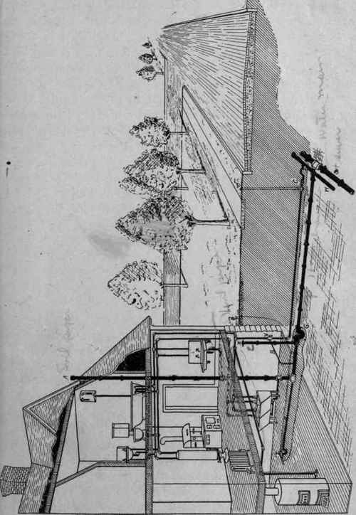
Fig. 58. - Cross-section of a city street showing the watermain and sewer pipe with their connections to a dwelling.
Next inside the trap is the vent pipe E, that extends to the surface of the ground. In this case it is just outside the basement wall. The top is covered with a metal cap. Another arrangement often made to accomplish the same purpose is shown in Figs. 61 and 62, where a piece of soil pipe in the form of a bend is made to take the place of the cap. Inside the basement and extending up through the partition walls to the roof is the waste stack or soil pipe A. This pipe as is explained in detail later, is made of cast iron and is put together with calked lead joints. The top of the stack at the point where it passes through the roof is shown in Fig. 59. In extending through the roof the pipe A must make a water-tight joint to prevent water from leaking through. This is accomplished by means of the metal plate D, which is set under the shingles and the piece C, that is soldered to D. The joint between C and A is best made with lead the same as the other joints of the stack. In the.case of very high stacks, the bottom should be supported by a pier or iron pipe rest. Besides being supported at the base the stack should be secured to the side walls or floor beams at each floor. This is to keep the pipe from moving out of place and the consequent opening of joints.

Fig. 59. - Detail of soil pipe connection.
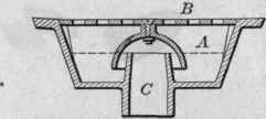
Fig. 60. - Cross-section of cellar-drain.
All of'the waste pipes from the bathroom, kitchen and basement drain into the waste stack. The cellar drain for draining the basement is shown at T in Fig. 58. It also appears in detail in Fig. 60. The plate B, in the latter figure, is set flush to the surface of a depression in the floor that serves as a collecting point for water. The floor is constructed to drain toward this point. The plate is perforated to let the water through and is generally hinged So that in case of stoppage the cover may be raised. The bell-shaped piece under the cover surrounds the piece C, to form a water seal when the level of the water is at A.
In addition to this water seal there is generally a trap between the drain and the sewer as shown in the drawing.
The method of connecting the bathroom waste pipes with the stack is shown in Fig. 99 and will be described later. All of the sewage of the house is emptied into the stack by the most direct route, and from the stack it is conducted as directly as possible into the sewer. From the drawing it will be seen that all openings to the sewer are sealed in two separate places, once at the outlet to prevent the air from the street sewer entering the house drain G, and again at each opening to prevent escape of the sewer gas from the drain into the house.

Fig. 61.

Fig. 62.
Fig. 61. - House drain with outside vent, and running trap placed inside the basement wall.
Fig. 62. - House drain with outside vent, and running trap placed outside the basement wall.
The openings at E and A at each end of the stack permit a constant circulation of air for ventilation. The length of the stack and its location causes it to act as a chimney and the draught produced takes the air in at E, and discharges it at the top. In large houses there is sometimes added a vent stack to produce further ventilation, but in the average dwelling the arrangement here shown covers the common practice.
In Figs. 61 and 62 are shown in detail two methods of arranging the sewer connections in the basement to permit of the removal of obstructions in case the pipes at any time become stopped. The trap, vent, etc., are easily recognized. With the arrangement as shown in Fig. 62, the clean-out is so placed as to give access to the inside of the pipe. Should an accumulation or obstruction of any kind become lodged in the pipe, the stop in the clean-out is removed and a flexible metal rod is used to remove the stoppage. The trap outside the wall has an opening through which the obstruction may be reached in case it cannot be removed from the first clean-out. The disadvantage in using the outside trap, as here shown, is that it can be reached only by excavation.
Fig. 61 shows another common method of installation. Here the trap is placed inside the basement wall. This gives an easier means of opening the trap than Fig. 62 affords and accomplishes the same purpose. The connections with the stack are the same as in Fig. 62. Obstructions in the sewer pipe are most likely to become lodged in the trap and for this reason the trap should occupy a position that is reasonably easy of access.
The outside trap as described above is quite generally installed in buildings of all kinds, but its use is by no means universal. In some communities it is not used at all, and many plumbers consider it only an added means of causing stoppage and an extra expense to install.
The object of the outside trap is to keep the air of the street sewer from entering the house drain. It is at once inferred that the air of the street sewer is more dangerous than that of the house drain. The street sewers, however, are ventilated at each street corner and at each manhole. There cannot then be much difference in the air of the two places. The traps on the fixtures that prevent sewer gas from entering the house would be just as efficient if the outside trap did not exist.
While the methods shown in Figs. 61 and 62 are considered good practice, there is considerable objection to the vent being placed near the dwelling, because of the sewer gas that is forced out, whenever a sudden discharge of water goes into the drain. Each time a closet is flushed, a large volume of water enters the stack and completely fills the pipe. When this occurs, the descending water forces out the air of the pipe ahead of it, and a gush of offensive air filled with sewer gases is forced out of the vent. It is evident that such a vent, located near an open window or where it will reach the nostrils of the inhabitants is a thing not greatly to be desired.
Outside traps when placed near the surface sometimes freeze.
The circulation of air through the vent is occasionally sufficient in cold weather to freeze the water and stop the trap.
Continue to:
My Books

