Traps
Description
This section is from the book "Mechanics Of The Household", by E. S. Keene. Also available from Amazon: Mechanics Of The Household.
Traps
The waste pipes from the wash basin and bath tub are always provided with some form of trap, to prevent air from entering the room from the sewer, charged with offending odors. Traps are made in many forms, but the purpose of all is to prevent the escape of sewer gas. The plain trap S, shown in Fig. 95, is that used under the basin in Fig. 91. It makes a tight joint by means of the nut B and a rubber washer as in the case of other joints of the kind. The parts C and E are unions that permit the pipe or bowl to be removed without disturbing the remainder of the plumbing. From the form of the trap it will be seen that the U-shaped part below the dotted line F will always remain full of water and so prevents the escape of air from the sewer. In case the trap becomes stopped the obstruction will likely become lodged in this part of the pipe. To clean the trap the screw-plug D is taken out with a pair of pliers and the obstruction removed with a wire.

Fig. 94.-Corner wash basin.
The traps used in Figs. 90 and 92 are the same in principle as Fig. 95 but are made to discharge into a pipe placed in the wall instead of under the floor. The trap in Fig. 94 is a form known as the bottle-trap that is sometimes used in the more expensive plumbing.
Another style much used with lavatories is the Bower trap shown in Fig. 96. In this trap the water comes down the pipe B and pushing aside the hollow rubber ball A, enters the space surrounding it and is discharged at C. The ball, being light, is held against the end of the pipe by the water and acts as a stopper to prevent evaporation from taking place. Open traps, such as Fig. 95, if left standing for a long time, may lose sufficient water by evaporation to destroy the water seal and allow the sewer gas to escape. In the use of the Bower trap such occurrence is much less likely to take place.
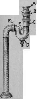
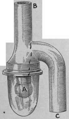
Fig.96.
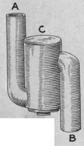
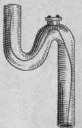
Fig. 95. - The S trap of nickel-plated brass tubing. Fig 96. - The Bower non-siphoning trap. Fig 97. - The drum type of non-siphoning trap. Fig. 98. - An S trap made of lead pipe.
Fig. 97 is another trap much used on sinks; it is known under the trade name of the Clean Sweep trap. The part C is much larger than the common trap and the water seal is less likely to be broken. The clean-out is larger and the interior is easy of access in case of stoppage.
The simplest and most commonly used trap in cheap plumbing is that of Fig. 98. It is a lead pipe bent in the form of an S. It is the same in shape as Fig. 95 and performs its work as well but does not have the means of detachment shown in the latter. Traps of many other forms are in use but all have the same function to perform and the mechanical make-up is much the same as those described.
The plan of attachment of the various bathroom fixtures of the soil pipe must always depend on local conditions. The object is to conduct the waste water to the sewer in such a way as to give the least opportunity for stoppage and to prevent sewer gas from escaping into the house. To accomplish this purpose the pipes and traps are arranged according to a plan proposed by the architect, plumber or other person familiar with the principles of plumbing. Since these pipes are placed in the walls and under the floors, where they are not readily accessible, it is necessary that their arrangement be made with care and that the workmanship be such as to assure correct installation.

Fig. 99. A method of bath-room plumbing using the drum trap.
In Fig. 99 is shown a common method of connecting bathroom fixtures with the sewer. The drawing shows a bathroom with the floor broken away to show the pipe connections with the bath tub, wash basin and closet. The overflow pipes 0 and V and the drain pipes D and R from the wash basin and bath tub empty into a large lead drum-trap T, set under the floor. This trap takes its name from its shape. It is set in position as dictated by the conditions under which it is used. The nickeled plate P, screwed into the top of the trap, comes just above the bathroom floor. This plate is easily removed in case of stoppage. It is made air-tight by a rubber ring placed under the cover and which makes a joint with the top edge of the drum.
It will be noticed that the waste pipes from the bath tub and wash basin enter the trap near the bottom and discharge at the opposite side near the top. The water will stand in the trap and pipes level with the bottom of the discharge pipe and thus form a seal that prevents the escape of sewer gas. This is a common form of non-siphoning trap. It is non-siphoning because it cannot lose its seal by reason of the siphoning effect of the water as it passes through the waste pipes on its way to the sewer. Another form of non-siphoning trap is the clean sweep trap shown in Fig. 97. Such traps as Figs. 95 and 98 are siphoning traps, since it is possible, in this form of trap, for the water to be, so completely siphoned that not enough remains to form a seal. The small drawing, marked Detail L, is another method of connecting the same arrangement of fixtures. The waste pipe enters the trap as before but discharges immediately opposite. The level of the water stands in the pipes as indicated by the dotted line.
Continue to:
My Books

