


Flush Tanks
Description
This section is from the book "Mechanics Of The Household", by E. S. Keene. Also available from Amazon: Mechanics Of The Household.
Flush Tanks
The water closet depends for its action on one of two general types of flush tanks, the high and the low forms. The tank is automatically filled with water and when wanted, a large volume of water is suddenly discharged into the sewer, carrying with it the contents of the seat. The tank again fills and is ready for use when required.

Fig. 105. - Siphon-jet closet with the high flush tank.
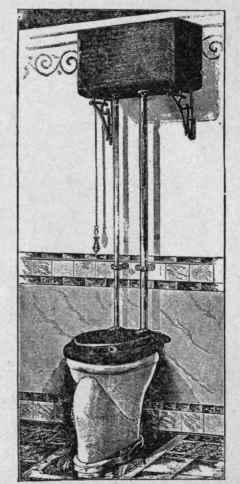
Fig. 106. - Form of closet not now used in good practice.
As illustrations of high flush tanks, those shown in Figs. 105 and 106 furnish examples of a simple and efficient form. The details of the mechanism of this type of tank are shown in Fig. 107. The pipe from the water supply is attached at G to the automatic valve F, which keeps the tank filled with water. The piece F of the valve is held against the opening by the pressure exerted through the float E. The float is a hollow copper ball.
As the ball is lifted it exerts a pressure in proportion to the amount it is submerged. When the water reaches the level A-A, the valve is tightly closed. As the water is discharged from the tank the ball follows the level of the water and opens the valve, allowing the water to enter and again fill the tank. The siphon is made of cast iron, and in the figure is shown cut through the center. The lower end fits loosely in the piece K, and makes a water-tight joint around its outer edge, by resting on a rubber ring C-C. The right-hand side of the siphon is open at H, and when the tank is full, the level of the water is at A-A, which is almost at the top of the division plate. To discharge the tank, the chain L, attached to the lever B, is pulled down; this action raises the siphon from its seat. As soon as the siphon is lifted, the water rushes through the opening around C-C, into the pipe K; this causes a partial vacuum to form in D, and the water is lifted over the division plate K, and flows out at D, forming the siphon. As soon as the siphonic action begins the siphon may be dropped back on the seat and the water will continue to discharge until the tank is empty.
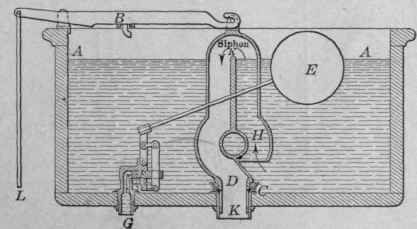
Fig. 107. - Details of construction of a simple type of siphon flush tank.
Low-Down Flush Tank
The low-down flush tank for water closets has met with so much favor that it has to a great extent displaced the high tank. The reason for this is because of its advantages over the other style. The low tank is more accessible, more easily kept clean, and better adapted to low ceilings. It is used successfully as a siphon tank, but other forms are in use with satisfactory results.
Fig. 108 gives a perspective view of one style of this type of tank attached to a siphon-jet closet. Figs. 109 and 110 give the details of the construction of two forms of this type of tank, both of which have given efficient service. The drawing shows the tanks with the front broken away to give a view of the working parts. The water enters the tank and is discharged at the points indicated. The float and supply valve works exactly as described in the high tank. The drawing in Fig. 109 shows the tank in the act of discharging. The discharge valve is raised as shown at E. When the water is completely discharged, the float occupies the position shown dotted. When the float reaches this dotted position, its weight pulls down the piece A. This releases the lever B, and the attached stopper E, which falls and closes the discharge orifice. While the tank is filling with water, a stream flows through the small pipe D, to replenish the water in the closet that has been discharged in siphoning. When the tank is full of water, the pieces A and B occupy the positions shown dotted, To discharge the tank the trip is pushed down. This action raises the lever to the position B, and with it the attached stopper E. The piece C falls and the opposite end A holds B suspended until the tank is completely discharged. The action of the tank shown in Fig. 110 is the same as the others except that of the discharge mechanism. In the drawing, the tank is full of water ready to be discharged when required,
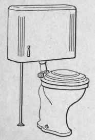
Fig. 108. - Siphon-jet closet with low-down tank.

Fig. 109. - Details of construction of low-down flush tank.
A hollow rubber ball E serves as a stopper for the discharge pipe. The ball is kept in place, when the tank is filling, by the pressure of the water above it. The discharge is started by pressing down the trip on the front of the tank. This raises the ball from its seat, and being lighter than water, it floats, thus leaving the discharge pipe open until the tank is empty, when the ball is again back on its seat. As the tank fills the pressure of the water above prevents the ball from again floating, until lifted from its seat. The supply valve and refilling pipe D is the same in action as in the other tank.

Fig. 110. - Details of construction of the float-valve, low-down flush tank.

Fig. 1ll. - Method of using the plumber's friend, in removing obstructions.
Continue to:


My Books

