The Wolpert Air Tester
Description
This section is from the book "Mechanics Of The Household", by E. S. Keene. Also available from Amazon: Mechanics Of The Household.
The Wolpert Air Tester
The purity of air is expressed by quantity of carbonic acid gas included in its composition. In order to determine the degree of purity of any atmosphere the amount of contained gas must be determined. This is accomplished by use of simple apparatus that may be successfully operated by those who are unacquainted with chemical analytical methods. The process is due to chemical action but the manipulation of the required apparatus is purely mechanical.
Fig. 165 shows the Wolpert air tester which is a form of this apparatus that has given general satisfaction. The results attained by its use are approximate but sufficiently exact for all practical purposes. The apparatus consists of a graduated glass tube in which fits a rubber piston mounted on a hollow glass rod, through which the sample of air is admitted to the tube. The chemicals used for absorbing the carbonic acid gas are furnished with the instrument but may be replenished without difficulty. Directions for its use are furnished with the tester that may be readily followed after a trial. The results obtained are read directly from the side of the tube. The tester may be obtained from any dealer in chemical or physical apparatus. Pneumatic Temperature Regulation. - Pneumatic temperature regulation is very generally used in large and complicated heating systems, because of its positive action and completeness of heat control. This method of heat regulation utilizes the energy of compressed air, with which to open and close the valves of the radiators. It may be adapted to any mode of heating and can be used with any size of plant, but is particularly suited to extended systems. The radiators, providing heat for any particular space, are under control of separate thermostats, which by means of motor valves admit heat only as required. A motor, operated by compressed air, is attached directly to each radiator valve. Any change in temperature of the room causes the thermostat to correct in the radiator the required amount of heat.
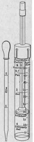
Fig. 165. - The Wolpert air tester; an instrument used to determine the quality of air.
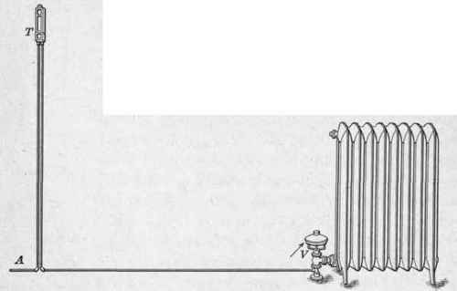
Fig. 166. - Thermostat regulator and motor-valve attached to a radiator.
With this method of regulation the temperature-controlling element of the thermostat, like that of the electro-thermostatic system, is a sensitive part, which by expanding and contracting with the heat and cold directly controls the heat in any part of the building. The motive power for opening and closing the valves of steam or hot-water radiators or for operating the dampers in a hot-air system is supplied by compressed air. The air supply is furnished by an air compressor which automatically stores air under pressure in a pressure tank, from which is drawn the necessary energy, as occasion demands. The air is conducted to the motors through small pipes which are connected with the regulating elements and also with the motors. The function of the thermostat is to so govern the air which enters the motor as to correct any change in the temperature of the rooms. This it does by opening and closing the valves as occasion demands.
In Fig. 166 is shown the arrangement of the thermostat T as it appears on the wall. Air from the supply tank is conveyed by the pipe A through the thermostat T to the motor valve V attached to the radiator. The function of the thermostat is that of so controlling the radiator valve by means of the motor V that the radiator will give out just sufficient heat to keep the room at the desired temperature. A closer view of the thermostat is given in Fig;. 167.
The thermostat illustrated in Fig. 167 is that employed by the National Regulator Co. The drawing shows the exterior and interior construction of the parts enclosed in the previous illustration. The pipe C at the right and opening P at the left are the same as A in Fig. 169; likewise, the pipe D connects at the opening M of the motor valve in Fig. 169.
Referring again to Fig. 168, the sensitive part consists of a tube A of vulcanized rubber. It is the dark-shaded part in the left-hand drawing. Any change in the air temperature influences the length of this tube. The changing length of the tube effects the air supply to close the radiator valve when the temperature rises above the desired amount and to reopen it when more heat is required. A finely threaded screw passes through the plug H at the top and to this is secured the indicating disc X. The bottom of this screw is cupped to receive the point of the rod K, which connects with the piece L. Any change in length of the sensitive tube moves the valve lever O, and thus opens or closes the air port G.
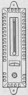
Fig. 167 - Outside view of thermostat as it appears in use.
Air under pressure is supplied by the pipe C, connected to the air supply, flowing into the thermostat through the filter P, the restriction S, the passage T, and the port G. The adjustment of the thermostat for different temperatures is provided for by the screw J through the top plug H, and the indicating disc X. The screw R in the connector Q at the base of the thermostat is a needle valve which opens or closes the connection with the air supply, and is used as an air shut-off valve when it is desired to remove the thermostat. The screw S is a restriction valve which controls the supply of air to the thermostat, and this screw is set so as to allow the air to pass in a restricted quantity.
When the temperature of the apartment has risen so as to expand the thermostatic element A, the pressure on K and L is relieved and the spring N closes the port G. The air admitted through the restriction screw S, since it cannot escape through the port G, accumulates in the passage Y and pipe D, filling the diaphragm and moving the valve into the position to decrease the supply of heat. When the temperature of the apartment has decreased so as to produce pressure on the connecting rod Kt through the contraction of the thermostatic element A, the port G will be opened by the valve lever 0, allowing the air in the pipe D, together with that which flows through the restriction 8, to escape through the passage W to the atmosphere, allowing no air to accumulate in the pipe D, and thus permitting the spring at the diaphragm to actuate the damper or valve for more heat. The amount of air released through the port G by the valve lever 0 varies the pressure accumulated in the pipe D and produces the graduated or intermediate action desired.
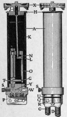
Fig. 168. - Internal construction of the National Regulator Co.'s thermostatic regulator.
A further application of air pressure in temperature regulation is that of the type of motor shown in Fig. 170. This device is intended to open and close dampers such as are used in the automatic regulation of temperature where heated air is used to warm the buildings. The operation of the motor is the same as that which controls the steam valve. The pressure exerted by the diaphragm is applied at A and the attachment to the damper is made at B. The motors indicated at V and N in Fig. 174 and D in Fig. 175 are examples of its application.
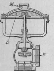
Fig. 169. - Cross-section of pneumatic radiator valve showing its internal construction.
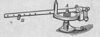
Fig. 170. - Pneumatic motor valve for automatic control of dampers, etc.
Continue to:
My Books

