117. Location Of Points (14-17)
Description
This section is from the book "Bench Work In Wood", by W. F. M. Goss. Also available from Amazon: Bench Work In Wood.
117. Location Of Points (14-17)
Location Of Points (-). All measurements must begin somewhere. The greater the number of points from which to begin, the more chances there are for mistakes. Thus in measuring from E to F, Fig. 136, there is one chance for a mistake. If G is located by measuring from F, then in the location of G there are two chances for a mistake, - one in locating F, another in locating G; but if G is located by direct measurement from E, there is, as in the case of F, but one chance of error.
1 Note
The material, or "stock," needed for the exercises of the course should be straight-grained, free from knots, well-seasoned, and machine-dressed. A good quality of either white pine or yellow poplar is to be preferred. Good work cannot be done in poor material.
By easy steps the operations to be performed become more and more difficult. The student should not advance to a new exercise until the preceding one has been completed in a good, workman-like manner. A failure, unless the result of accident, should invariably be followed by another trial of the exercise. Otherwise, a careless habit is encouraged.
The course may appear brief, but experience has demonstrated its completeness as a preparation for constructive work in any of the lines to which it leads. After the fifteen exercises have been finished, if time remains, any ordinary piece of bench work may be undertaken.
Fig. 136

Side Elevation (Face A).
End Elevation.
In locating a point by measuring from a point or line already fixed, it is necessary to make some kind of mark to indicate the distance. Haste in such work frequently results in a mark similar to that shown at E, Fig. 136, a "point" through which a line may be drawn with ease but with doubtful accuracy. A dot from a sharp pencil, as shown at F, Fig. 136, is much better; but if by reason of roughness of surface such a dot is too indistinct, two lines meeting each other at an angle may be used, G, Fig. 136, the point of juncture indicating the required location.
118. A Jointed Face is a surface that has been made a true plane. The necessities of practice so often require jointed faces at right angles to an adjoining face, that to many the term has come to mean not only a true plane, but such a surface at right angles to another, from which it is said to have been "jointed."
119. A Working-Face is one selected as a guide for operations to be performed on an adjoining face. For accurate work the working-face must be jointed. At this face, all measurements have their beginning, and by it all lines are produced. If a piece of material is to receive lines on two opposite sides, as A and C, Fig. 136, either B or D may be used as a workingface, but not both; if it is to receive lines on four faces, as A, B, C, and D, two of them, as A and B, for example, must be working-faces; if on six faces, three must be working-faces. For example, suppose lines are to be made on the surface A, Fig. 136, from B as a working-face; those running across the piece, as ab, will then be made perpendicular to B, and those running lengthwise, as cd, parallel to B. If, on the contrary, the working-face is disregarded, and some of the lines are made from B and some from D, their truth will depend not only on the truth of B and D as individual surfaces, but also upon their parallelism, and hence there is a double chance of error. Only one face, therefore, should be used from which to do the lining for a given surface. If lines are to be made on all four sides, as A, B, C, and D, and A and B are the working-faces, all lines on A and C can be made from B, and all lines on B and D can be made from A. It will be seen, therefore, that in making a piece a true square in section, it is necessary to use the beam of the square on only two faces.
Exercise No. 1. - Measuring and Lining.
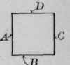
120. The stock required is 1 3/4 inches thick, 4 inches wide, and 4 feet long, or, as usually written, 1 3/4" x 4" X 4'. Fig. 137 shows the completed exercise.1 To aid in following directions, it will be well to letter the four faces of the work A, B, C, and D, respectively, as indicated by Fig. 137 (End Elevation), and to mark two of them, as A and B, working-faces.
Operations to be performed on Face A, from B as a Working-Face, Fig. 137.
Continue to:
My Books

