129. Lining With Scriber And Bevel
Description
This section is from the book "Bench Work In Wood", by W. F. M. Goss. Also available from Amazon: Bench Work In Wood.
129. Lining With Scriber And Bevel
Lining With Scriber And Bevel. Set the bevel at an angle of 45 degrees and, using it as before, scribe lines from the try-square lines, as shown by bc, ad, etc.
130. Gauge-Lining (32-35). The gauge provides the most ready means for the accurate production of lines parallel to a working-face. As shown in Fig. 143, the beam of the gauge B carriesa steel spur C, which does the marking. B also carries a heads, which is adjustable on the beam.
Fig. 143
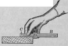
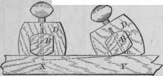
To use the gauge, adjust the head so that the distance between it and the spur C is equal to that between the working-face and the required line; then close the fingers over the head and extend the thumb on the beam towards the spur, as shown by Fig. 143. Holding the gauge in this manner, bring the head against the working-face, move the gauge along the work, and the line will be produced. To prevent the spur from sticking, the first stroke should make a light line, which may be strengthened by a second, and even a third passing of the gauge The depth of the line in each case is regulated by turning the gauge as indicated by the relative position of Y and X, Fig. 144. It is obvious that no spacing is necessary when this tool is to be used.
By use of the gauge, lay off 1/8" apart the lines fh, eg, etc., Face D, Fig. 137.
Fig. 144
Operations to be performed on Face C, from B as a Working-Face, Fig. 137.
131. The lines on this face are to be used in Exercise No. 3. By applying the principles already developed (121, 122) locate the lines as shown by the drawing, Face C, Fig. 137. This work may be done with the pencil, the lines ab and a'b' being "gauged" by use of the rule (126). The line cd, End Elevation, may be made in the same way.
Fig.145

Exercise No. 2. Practice with Chisel and Gouge (39, 40, and 42).
The stock required is 7/8" X 4 1/2" X 8".
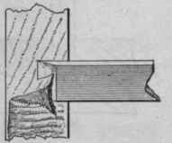
Fig. 145 shows the lines that are needed, all of which are produced as explained in the foregoing exercise, except the arcs of circles, which must be put in with the dividers (26); A and B are working-faces. An end elevation of the finished piece is represented by Fig. 146.
Fig.146

132. To remove the Portion abc, Fig. 145. - It is always best, in removing surplus wood with the chisel, to cut across the grain, as any attempt to carry the cutting edge along the grain is quite sure to result in a splitting action, the chisel following the grain of the wood, which splits ahead of it, and prevents the operator from controlling its course. In removing the portion abc, the work should be held in the vise with the working-face A toward the operator. A 1" chisel will be found of convenient size. Beginning at one end, make successive cuts with the chisel, as shown by Fig. 147. Each stroke of the chisel should cut almost to the full depth required (i.e. remove a shaving from the face of nearly the whole triangle abc), the thickness of the cutting varying with the character of the material and the strength of the operator. It is best, however, to go slowly, for the chisel will not be properly guided if the workman's whole strength is required to push it through the wood. The surface thus produced will not be smooth, but it will be true to the line. To smooth it, a wide chisel should be used, as shown by Fig. 148, and a longitudinal movement imparted to it at the same time it is being pushed forward.
Fig. 147

Elevation.
Plan.
It will be noticed that both chisels are applied to the work in such a way as to turn the shaving from the bevel, and not from the flat face. This is done that the flat face may be available as a guiding surface, which, when kept in contact with the solid material back of the cut (see b, Fig. 148), will insure straightness in the forward movement of the cutting edge, and, consequently, accuracy of work.
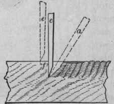
133. To remove the Portion defg, Fig. 145. - With the work flat on the bench, face A uppermost, place a 3/8" chisel so as to bring its cutting edge in the position occupied by the line hi, which is about 1/8" from the end of the work. With the mallet, drive the chisel vertically downward, as indicated by c, Fig. 149. When down to the depth of the required cut, the chisel should be pushed over to the position a, to make room for the next cut, after which it may be withdrawn and placed in position again at e. This operation is to be repeated until the whole length of the piece has been passed over, making the work appear as indicated, in part, by Sec. AB, Fig. 149. The cuttings may then be removed. The sides of the opening will be even and fairly smooth. The distance the chisel is advanced (/) must depend on the material, and the depth to which it is driven; it should never be so great as to risk the breaking of the chisel when it is moved from position c to a.
Fig. 148

Fig. 149

Plan.
Section A B.
To remove the portion jkon, Fig. 145. - Using the chisel as in the last exercise, remove the portion jklm, and afterwards the portion Imon.
134. To remove the Portion pqr, Fig. 145. - This is done with the gouge, which, unlike the chisel, may be used with the grain, as indicated by Fig. 150, the concave surface of the work allowing its individual fibers to give greater support to one another in resisting a splitting tendency. It will be seen that the bevel of the gouge is its only guiding surface. This being necessarily short, the tool is a difficult one to use. Light cuts should be taken, especially when the grain of the wood is not favorable.
To finish Exercise No. 2. - By use of the chisel round the part between the lines fg and no, and also the part between the point m and the line ks, to agree with the finished form shown by Fig. 146, and smooth all chiseled surfaces not already finished.
Exercise No. 3. - Sawing (49-55).
The stock required is the finished piece from Exercise No. 1; it is to be cut as indicated by the lining on Face C, Fig. 137.
Continue to:
My Books

