203. Mortise-And-Tenon Joints
Description
This section is from the book "Bench Work In Wood", by W. F. M. Goss. Also available from Amazon: Bench Work In Wood.
203. Mortise-And-Tenon Joints
Mortise-And-Tenon Joints. A tenon is a projection made on the end of a timber to form part of a joint; a mortise is an opening intended to receive a tenon. In Fig. 243, T is the tenon; M, the mortise; R, the root of the tenon; S, S, its shoulders; and c, c are sometimes called the "abutting cheeks" of the mortise.
Fig. 242

Fig. 243

204. When a vertical timber meets a horizontal timber the object of the joint is simply to prevent displacement; and a small, short tenon, sometimes called a "stub tenon," is usually employed. In this case, the tenon should not reach the bottom of the mortise, but the strain should be taken by the shoulders. Sometimes, instead of making a stub tenon, the whole end of one timber is let into another, and the first is then said to be "housed."
Fig. 244
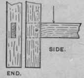
Fig. 245

205. When a horizontal timber meets a vertical timber the joint may be formed as shown by Fig. 244, or made much stronger, if, in addition to the tenon, it is "blocked," Fig. 245, or housed, as shown by Fig. 246.
206. When one horizontal timber meets another it is a common practice, if the proportions of the pieces are favorable, to employ a double mortise-and-tenon, Fig. 247, A being supported by B. This method cannot be recommended, however, because B is very much weakened by the mortises. With reference to B only, the best place for the mortise is on the neutral axis (in the center of the timber); while with reference to A only, the tenon should be on its lower edge, that it may be re-enforced by all the material above it. If timbers of equal depth are thus joined, they will appear as shown by Fig. 248; but this combination, while strong, is not always practicable because of surrounding conditions. For this reason both mortise and tenon are often placed in unfavorable positions, and the strength of the joint sacrificed. Sometimes the form shown by Fig. 249 is used, but this has little in its favor, except the ease with which it is made. A better combination is shown by Fig. 250, which, although less perfect as a joint, may serve the purpose quite as well as Fig. 248, if the timber is long between supports. Tusk tenons are used to overcome the difficulties presented by the forms already described when employed in heavy construction. This arrangement of surfaces, Fig. 251, allows the mortise to be in the center of the timber, and to be small; and it also allows the tenon, by means of the tusk T, to present a low abutting surface on the supported timber. Its strength and compactness fully compensate for the difficulty of fitting it.
Fig. 246
End.

Side.
Fig. 247

Plan.

Elevation.
Fig. 248

Fig. 249

Fig. 250

Fig. 251

Fig.252.

Miscellaneous Joints.
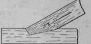
207. Oblique Mortises and Tenons may be used to join two timbers meeting each other at an oblique angle. Fig. 252 shows a common form in which the abutting surface, represented by the dotted line A, is perpendicular to the cheeks of the mortise, and the stress transmitted in the direction of the arrow is divided between the surfaces represented by the dotted line A and the full line B. A bearing along the latter line becomes unreliable when the timbers shrink, or when, by the settling of connected parts, the surfaces change their relative position. For this reason it is better to depend mainly on the line A, which is less affected by the causes mentioned. To take all of the stress, this line should be at right angles to the length of the tenon-bearing timber, Fig. 253. This, however, while apparently a well-formed joint, is not a strong one, for the tenon, which is usually equal to but one-third the width of the timber, must alone receive the thrust. To relieve the tenon by increasing the area of the abutting surface, the end of A may be housed, as shown by Fig. 254, or the joint may be strengthened by bolts or straps.
Fig. 253

Fig. 254

Fig. 255

End.

Side.
Fig.256
End.
Side.
The mortise for the joint shown by Fig. 253 is usually made of the outline abc, and the triangle a'bc is not filled. This is done because it is easier to cut down the line be than the line a'c. There seems to be no objection to this practice.
208. A Bridle Joint is represented by Fig. 255. It possesses the advantage of having its parts so exposed that any inaccuracy in the fit is always apparent. An oblique form of bridle joint, Fig. 256, is certainly worthy of study. The width of the bridle, B, Fig. 255, should not exceed one-fifth the width of the timber.
Fig. 257

End.

Side.
Fig. 258

209. A Tie Joint is shown by Fig. 257. By the insertion of the tie B, the timber A is prevented from falling away in the direction indicated by the arrow. The joint illustrated by Fig. 197 may be made to serve the same purpose.
210. A Chase Mortise is a mortise elongated as shown by Fig. 258. Its purpose is to admit a cross-timber between two timbers already fixed. When the cross-timber is in place that portion of the mortise which is unoccupied may be filled, and the joint thus made secure.
Continue to:
My Books

