Finishing The Box
Description
This section is from the book "Bench Work In Wood", by W. F. M. Goss. Also available from Amazon: Bench Work In Wood.
Finishing The Box
With the smooth-plane take a light cut all over the outside, keeping the sides and ends square with the bottom and with each other. The ends of the box, where the end grain of the bottom and side pieces is encountered, present the most difficulty.
Fig. 174

154. In planing end grain, the cutting edge must be sharp and set to take a fine shaving. If only a little material is to be taken off, the movement of the plane should be so limited that the cutting edge will not extend beyond the work, two cuts being taken in opposite directions, as indicated by A and B, Fig. 175. The motion of the plane in both directions, ceases near C. If much is to be removed, and it seems best to carry the plane the entire length of the surface, a bevel may be made which will allow the cutting edge of the plane to leave the work gradually, and at a little distance from the edge, as shown by Fig. 176, or a piece of waste material may be fixed with it in the vise as shown by Fig. 179.
Fig. 175

Fig. 176

Exercise No. 6. - Bench-Hook (12).
The stock required is 1 3/4" x 2 3/4" x 16" from Exercise No. 4. It is shown with the necessary lining by Fig. 177, in which figure the Plan, face A, represents the working-face, and the Elevation, face B, the working-edge. The finished piece is shown by Fig. 178.
155. Lay off the lines ab and cd on face B, Fig. 177. Project ab across face A, as shown by ae, and project cd across face C (not shown), and from these, project on face D lines similar to ab and cd, which are already located on B. Locate the point i on lines ab and cd, and also on the similar lines of the opposite face D, measuring in each case from the workFig. 177 Scale 1 1/2=1 Scale, 1 1/2=1 ing-face A, as indicated by the dimensions given. By use of a straight-edge, draw ij and ik, and similar lines on the opposite face.

Plan (Face A.).

Elevation (Face B.).

End.
Fig. 178

Cut along the lines ij and ik with the rip-saw. There are two ways of starting the saw when the material, as at k, is not sufficient to hold the blade. First, a saw cut may be made along the line cq, and the triangle cqk chiseled out, giving a flat surface, cq, on which to begin; secondly, a block of wood of the same breadth with the work may be fastened in the vise with the latter, as shown by Fig. 179, thus, in effect, extending the surface ok. In the case of the line ik, the second plan is preferable. The block A should bear well upon the work B at k.
The lines if and ik having been sawed, cut di and ai with the back-saw. With the chisel produce the bevels represented by mn and op. Bore the hole R, Fig. 178, and the piece is finished.
156. With reference to R, it may be said that while an auger-bit (89) will cut smoothly when entirely within the material, it is sure to splinter when coming out on the face opposite the starting point.
To prevent this, the bit may be used from one side until its spur appears on the opposite side, and then withdrawn, and started in the opposite direction in the hole left by the spur; or the work may be held firmly to another block, as shown by Fig. 180, and the bit allowed to pass into the block as though the two were one piece.
An auger-bit should cut freely, and advance into the work without much pushing on the brace; if it does not, it is in poor condition and should be sharpened.
Fig. 179

Fig. 180

Exercise No. 7. - Halved Splice (202-203).
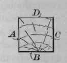
The stock required is 1 5/8" X 1 5/8" X 16" from Exercise No. 4; it is shown with the necessary lining, by Fig. 181. The completed piece is shown by Fig. 182.
157. A and B, Fig. 181, were marked as working-faces when the piece was planed, and may be used as such in this exercise. Midway between the two ends on face A, locate the line a, and from a locate b, c, d, and e. Produce each of these lines across all four faces of the piece. Set the gauge at 13/16" (half of 1 5/8" the width of the piece), and from the working-face A, gauge a line from b on face B around the end, and back to b on face D; also from line d on face B around the opposite end to line d on face D. These lines are shown on face B by fg and ij. The joint is made by cutting out the rectangular pieces bhgf and ijlk.
158. In cutting a splice, both pieces are not taken from the same face, for the reason that the gauged line may not be exactly in the middle, and in that case each of the remaining parts would be more than half or less than half the thickness of the material, and their united thickness, when put together, as in Fig. 182, would be greater or less than the material else where. The pieces cut out, therefore, are from opposite faces. Then if the gauge line is not in the center of the piece, that is, if bhgf is thicker than ijlk, the smaller piece will be taken out on one side, and the larger piece on the other; and the sum of the two remaining parts when put together, as in Fig. 182, will be equal to the full size of the material.
Fig. 181 Scale, 3' - l' plan. Face A.


Elevation. Facc B.
End.
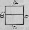
Fig. 182

Elevation. Facc B.
159. To cut the pieces, first run the rip-saw down the lines gf and ij; next, with the back-saw, cut the lines bf and lj; next the lines c and e, being careful in all of these cuts to keep the proper side of the line (148). Finally, cut on the line a, and try the pieces together as in Fig. 182. If the work has been well done, the joint will be good. If it is not good, the faults may be corrected. The cuts gf and ij, if not quite to line, may be brought to it by using the chisel as shown by Fig. 147. To faciliFig. 183 tate the operation, make chamfers on each side from the line to the sawed surface, as shown by Fig. 183, to be used instead of the line. Such chamfers present a twofold advantage; they are both visible from the same point, and they prevent splintering on the side on which the chisel comes out. The fitting on the line ab, Fig. 182, having been finished, suppose that the heading-joint ac fits, but that bd does not; or suppose that neither fits properly, as shown by Fig. 184. If the discrepancy is not great, the joint may be corrected by use of the chisel, or it may be sawed to a fit.

160. "To saw a Fit," the two pieces should be clamped together, or held by hand in the position shown by Fig. 184, and the joint at c sawed into. This will make c at least as wide as the saw kerf. Without changing the relative position of the pieces, turn the work over and saw d, which will also become at least as wide as the saw kerf, and, consequently, equal to c in so far as the joints have been affected by the saw. If in each case the joint is close enough to hold the saw, the pieces after sawing will come together perfectly. If one sawing is insufficient, the pieces may be brought together and sawed a second, and even a third time.
This method of fitting may be widely applied.
When the joint is perfect, the pieces are to be nailed at each end with 4-penny casing nails driven obliquely, or "toed," as illustrated by Fig. 185. While nailing, rest the pieces A and B on the bench C, and, to retain them in position, allow one to bear on the block D, which in turn is held by the bench-stop. The block protects the ends of the work, which would be mutilated by the bench-stop if they were placed in direct contact with it.
Fig. 184
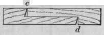
Fig.185

Continue to:
My Books

