Plates and Illustrations. Part 6
Description
This section is from the book "Modern Carpentry And Building", by W. A. Sylvester. Also available from Amazon: Modern Carpentry And Building.
Plates and Illustrations. Part 6
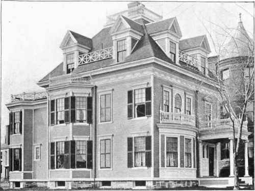
A FINE MODERN RESIDENCE. (For floor plans of similar houses see back part of this book.)
Plate 17.
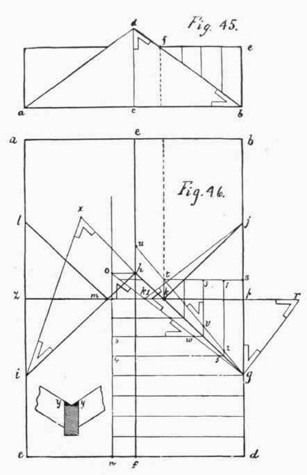
Sometimes the ridge of the cross roof is carried clear through from z to p; in this case the valley rafters are all of the same length. The plan of them would be gk, jk, im, and lm, their actual length being gt; and the edge bevel of the top of the valley rafters is the angle formed by the lines gt and st. dgno is part of the roof laid down flat, the edge being kept even with dg; now, if n o is raised equal to c d (Fig. 45), it will stand just plumb over fh; and the hip rafter og will stand plumb over the plain of the valley hg. g t s is one side of the cross roof laid down flat, the foot of the rafter s g being kept even at g; now, if t s is raised the height of e b (Fig. 45), the end s of the rafter g s being kept plumb over the plate d b, then s t will stand plumb over k p, and the lines o g and u g will meet, and stand plumb over h g; the points t and k 1 will meet plumb over k.
The line of the top side of the jack rafters must run to the centre of the edge of the valley rafters; and bevelled strips may be nailed along on each corner of the upper edge of the valley rafter, so as to continue the slant of the roof from the end of the jack rafters to the centre of the edge of the valley rafters, as shown at y. In laying out such work as this, it is well to draw it to as large a scale as possible, using a hard pencil, sharpened fine, and work accurately: since, if your drawing is 1/10 size, a variation in the drawing of 1/16 of an inch will cause a variation of 5/8 of an inch in the work; errors in the drawing being magnified ten times in the work.
Plate 18. Fig. 47 shows a frame of a mansard roof; a being the studding of the house, b the ledger boards, c the floorings, d the plate of the house, e the mansard rafter, f the roof-plates, g the rafter of the hip roof; h represents pieces of plank fastened to the studding, being boarded across and tinned on top, the gutter being nailed to the outside ends, thus forming a coving. A French roof is usually formed by nailing sweeps, t, which are made of plank, to the straight rafters e. Fig. 48
Plate 18.
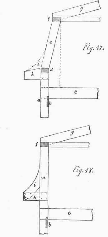
shows another method of forming a French roof. By this method the outside studding runs to the hip roof, the sweeps for the French roof being fastened to these studs. This method gives rooms in the roof of the same size as those in the story below; and, if properly proportioned, it makes a very good-looking roof.
Plate 19. Fig. 49. To describe the corner rafter on a French roof. - Let L c m represent the plan of a corner of the building, which in this case is square. Bisect the angle L c m (see Plate 1, Fig. 2), which gives the line g c, which is the centre line of the plan of the rafter, on each side of which lay off half the thickness of the corner rafter. Draw the line c b square with the line L c. Measure off from the line L c, the perpendicular length (not the length on the slant) of the straight rafter e, and draw the line a b square with b c. On this line a b, measure off from b to f the amount which the straight rafter tumbles in. Now place one of the common curved rafters against the line of the straight rafter cf; and, keeping the bottom of the rafter on the line a b, mark out the shape of the common curved rafter. Now draw the lines 1, 2, 3, 4, 5, 6, parallel to b c from various points of the curve, running them to the centre line of the plan of the angle rafter g c. Then draw these lines square from the line g c, making the length of the line 1 a to D the same as the line 1 from d to the line Lc; and making the line 2 a the same length as the line 2 to the line L c, and so on. Draw a curved line from D through these points to E, which gives the curve of the edge of the angle rafter (from E to c will be straight). Make D A the length of d a. The line c B is drawn from the point e, square with the line eg; the line c B being drawn the length of cb. Join. A and B, and we have the shape of the corner of the roof plumb down from the top of the straight rafter e. Line 5 runs to f, the foot of the straight rafter: so the line 5 a will determine the position of the foot F of the straight angle rafter. The line 6 runs from e, the top of the curved rafter, so the line 6 a will run to E, the top of the corner curved rafter. Then the shape of the corner curved rafter is E D A F. To find the splay, or chamfer, draw lines parallel to 1 a, 2 a, etc., from the point where the lines 1, 2, etc., pass through the line representing the edge of the rafter g e. Also draw lines square from the ends oil a, 2 a, etc., to these lines. Now draw a curved line from D through the points of intersection, and we have the amount necessary to chamfer the rafter. The length of the straight corner rafter is from e to F, which is somewhat more than the length of cf: and it is set with the centre of its edge exactly even with the corner of the building, as shown in Fig. 50 at b; 1, 2 being the sides of the rafter, a b c being a plan of the corner of the building, and R being the curved rafter. If it is desired not to chamfer the edge of the corner curved rafter, it must be sawed on the line of the chamber Dx; and y would be the foot of the straight rafter. In this case, the straight rafter must be set with its corners even with the edge of the plate, as seen at 5 6, Fig. 50; that is, providing the thickness of the corner straight rafter is the same as the thickness of the corner curved rafter. Should the straight rafter be thicker, then gauge off the thickness of the curved rafter in the centre of the edge of the straight rafter, and let the lines representing the thickness of the curved rafter come even with the edge of the plate, as seen in Fig. 50; 3 4 7 8 represents a thick, straight rafter 5 6 being the thickness of the curved rafter, which points are set even with the edge of the plate. But if the corner curved rafter is chamfered, then the corner straight rafter must be set out even with the corner 5, so that the points 5 6 would be in the place occupied by 1 '2; and as much of the straight rafter as is above the curved rafter must be chamfered to correspond with the chamfer of the curved rafter. This rule applies for external and internal angles, whether the}' be acute, obtuse, or right angles. One thing, however, must be observed: that is, the rafter must be stayed from the building at the angle eg, found by bisecting the angle formed by one corner of the building. Otherwise, it will not coincide with the line of the roof on both sides. This rule is also used for getting the angle brackets for large cornices, where they are lathed and plastered, and for getting the angle rafters for groined arches, etc.
Continue to:
My Books

