Plates and Illustrations. Part 9
Description
This section is from the book "Modern Carpentry And Building", by W. A. Sylvester. Also available from Amazon: Modern Carpentry And Building.
Plates and Illustrations. Part 9
A board may be divided into any number of equal parts in a similar manner. If it is desired to divide the board into 10 equal parts, have the corner of the square even with one edge of the board, and have 20 inches come even with the other edge; then mark off every 2 inches. If 7 parts were desired, make 21 inches even with the other edge, instead of 20 inches, and mark off every 3 inches instead of every 2 inches.
Figs. 75 and 76 illustrate a very simple and also a very accurate method of fitting, down thresholds. Take any board 5 or 6 inches wide, as 6, Fig. 75, and 2 or 3 inches longer than the width of the doorway d. Lav this board on the floor, keeping the edge of the board one inch from the door-frame; lay a short straight-edge (2 feet square) against the door-jamb, and mark on the board where it crosses: also lay it against the £6 rebate of the jamb, and mark on the board where it crosses; repeat the operation on the other door-jamb. Now draw back this board, and substitute the threshold in the place of the door-frame, keeping the upper corner of the threshold one inch from the edge of the board, as seen in the shaded section in Fig. 76; and continue the lines from the board b on to the threshold t. Now all that remains to be done is to gauge on to the threshold the depth of the rebate. If carefully done, the threshold will be a perfect fit every time. A hard pencil sharpened fine, or, better still, a knife, should be used in marking.
Plate 32.
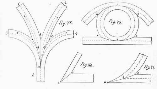
Fig. 77 represents a round chimney or flagstaff, a, passing through a slanting roof: the shape of the opening in the roof will be oval, as shown at c.
Plate 32 shows the mitring of straight and circular mouldings. Fig. 78 shows four circular mould-ings, mitred together so as to form one moulding, as shown at A. The centres of all these mouldings come together at a. The mitre joint where 1 and 2 come together is a straight line, b a. The mitre where 2 and 4 come together is a curved line, one end of which is at the intersection of the edges of the moulding at e; the other end is at the intersection of the centre lines at a; the amount of curvature is found by the intersection of lines e and f, running midway between the centres and the outsides of these mouldings, the intersections being at d. Now, with these three points, a, d, and e, find the centre of a circle, the circumference of which will pass through them. (See Fig. 9, Plate 3.) Figs. 79 and 81 are other illustrations of the mitring of straight and circular mouldings. The intersection of the outsides at a and c, and the intersection of the centre lines at b, give three points, with which find a centre as before. Fig. 80 shows a wide and a narrow strip of board mitred together: the intersection of the outsides gives the angle of the mitre. It should be remarked that the mouldings in Figs. 78 and 79 must be the same shape each side of the centres, such as are called double mouldings.
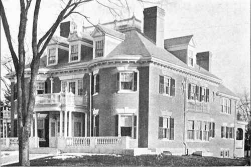
A COLONIAL STYLE RESIDENCE OF BRICK. (For floor plans of similar houses see back part of this book.)
Plate 33
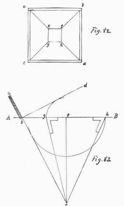
Plate 33 shows the method of finding the bevels for a hopper-box having butt joints. Fig. 82: a b c d is the plan of the top of the box, and efg h is the plan of the bottom. Fig. 83: A B is the line of the bottom of the box; a b is the slant of the sides, which line continue indefinitely toward c. Draw the line d b at right angles with a b. At any point on the line A B, as at f, drop a perpendicular line until it intersects the line a c. Now with f as a centre, and a radius tangent to the line a c, cut the line A B at h; join hc; at h is the bevel to cut the sides. Then, again, with f as a centre, and a radius tangent to b d, cut the line A B at g. Join g c; at g is the bevel to cut the edges, the stock being jointed square on the edges.
Plate 34 shows the method of finding the bevels for a hopper-box with mitre joints. Fig. 84: a b c d is the plan of the top of the box, and efgh is the plan of the bottom. Fig. 85: Let a b c be one corner of the plan of the box, and b d be the slant of the side. Draw the line d.f at right angles with the slant of the side b d. Bisect the angle a b c, getting the line b e, which would be the mitre for the edges if the sides were perpendicular; but as the sides slant, the correct mitre is found by erecting a perpendicular on the line b c, as at h, continuing it until it intersects the line b e. Now, with h as a centre, and a radius tangent to b f, cut b c at g. Join g e. At g is the mitre for the edge. Then with h as a centre, and a radius tangent to b d, cut the line b c at c. Now join c e. At e we have the bevel to cut the sides.
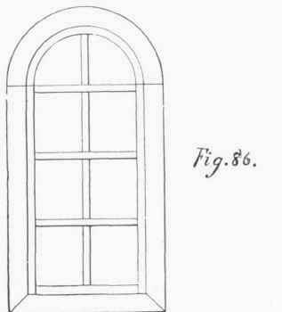
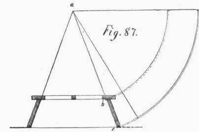
Plate 35. Fig. 86 is an elevation of a splayed circular-top window. Fig. 87 shows the method of finding the form of a board to spring around the splayed circular top on the inside, the principle being the same as finding the envelope of a truncated cone (See Plate 7, Fig. 21); the bevel of the sides being continued till they intersect at a, which is the point to use as a centre, to describe the form of the board.
Plate 34.
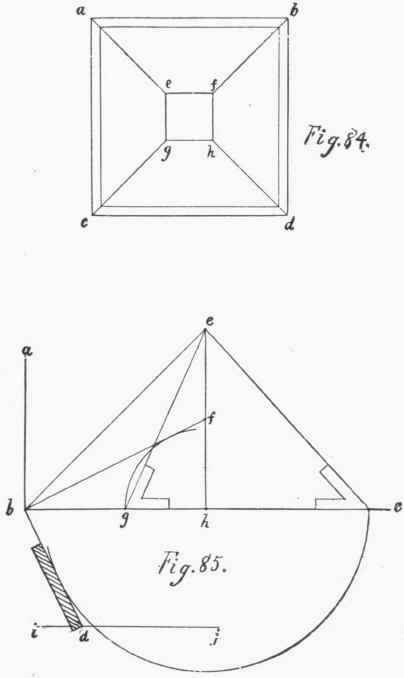
Plate 35.
Continue to:
My Books

