Drawing And Its Utility. Part 3
Description
This section is from the book "Carpentry for Boys", by J. S. Zerbe. Also available from Amazon: Carpentry for Boys.
Drawing And Its Utility. Part 3
Illustrating Cube Shading
In Fig. 137 I show merely nine lines joined together, all lines being of equal thickness.
As thus drawn it may represent, for instance, a cube, or it may show simply a square base (A) with two sides (B, B) of equal dimensions.
Shading Effects
Now, to examine it properly so as to observe what the draughtsman wishes to express, look at Fig. 138, in which the three diverging lines (A, B, C) are increased in thickness, and the cube appears plainly. On the other hand, in Fig. 139, the thickening of the lines (D, E, F) shows an entirely different structure.
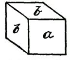 Fig. 137.
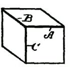 | 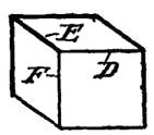 |
Fig. 138. | Fig. 139. |
It must be remembered, therefore, that to show raised surfaces the general direction is to shade heavily the lower horizontal and the right vertical lines. (See Fig. 133.)
Heavy Lines
But there is an exception to this rule. See two examples (Fig. 140). Here two parallel lines appear close together to form the edge nearest the eye. In such cases the second, or upper, line is heaviest. On vertical lines, as in Fig. 141, the second line from the right is heaviest. These examples show plain geometrical lines, and those from Figs. 138 to 141, inclusive, are in perspective.
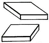 | 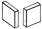 |
Fig. 140. | Fig. 141. |
Perspective
A perspective is a most deceptive figure, and a cube, for instance, may be drawn so that the various lines will differ in length, and also be equidistant from each other. Or all the lines may be of the same length and have the distances between them vary. Supposing we have two cubes, one located above the other, separated, say, two feet or more from each other. It is obvious that the lines of the two cubes will not be the same to a camera, because, if they were photographed, they would appear exactly as they are, so far as their positions are concerned, and not as they appear. But the cubes do appear to the eye as having six equal sides. The camera shows that they do not have six equal sides so far as measurement is concerned. You will see, therefore, that the position of the eye, relative to the cube, is what determines the angle, or the relative angles of all the lines.
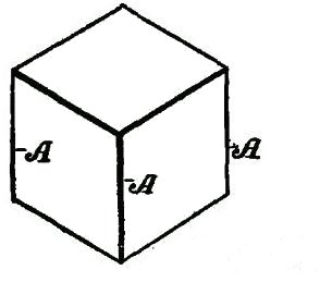 Fig. 142.
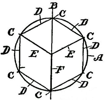 Fig. 143.
A True Perspective Of A Cube
Fig. 142 shows a true perspective - that is, it is true from the measurement standpoint. It is what is called an isometrical view, or a figure in which all the lines not only are of equal length, but the parallel lines are all spaced apart the same distances from each other.
Continue to:
My Books

